How to Complete an Electrical Installation Certificate
The Electrical Installation Certificate (EIC) is required for all new electrical installations, additions to existing installations, and alterations that include the provision of a new circuit. This guide walks through every section of the form so you can complete it accurately and issue it to your client.
Before you begin
An EIC covers new installations and any work that involves a new circuit. If the work does not include a new circuit, you may only need a Minor Works certificate instead. The EIC requires separate sign-off from the designer, constructor, and inspector - though in practice these are often the same person.
The certificate is split into nine parts: details of the installation, design, construction, inspection and testing, particulars of signatories, supply characteristics, particulars of the installation, schedule of inspections, and comments. You also add one or more distribution boards with circuit-level test results. You can save your progress at any time and come back later.
Getting started
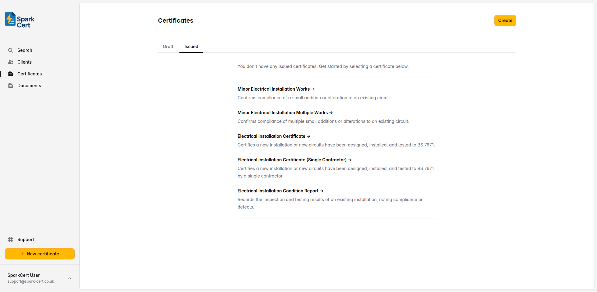
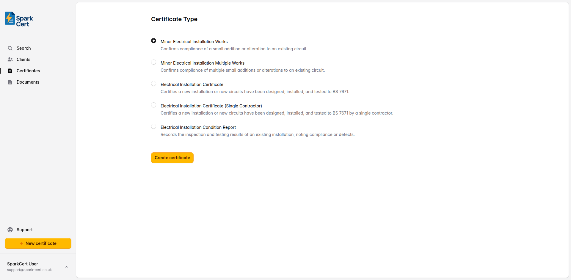
Navigate to Certificates → Create and select EIC as the certificate type. If you don't have any certificates yet, the type selection will appear directly on the certificates page; otherwise you'll be taken to a separate form. Choose the client and installation address for the job. If the client doesn't exist yet, you can create them inline without leaving the form.
Certificate details
After selecting the certificate type, you'll be taken to the create form. Here you set the basic details before moving on to the certificate itself.
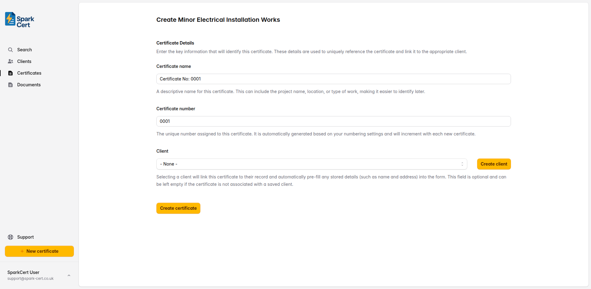
A descriptive name to help you identify the certificate later. This could be the project name, location, or type of work. A default is generated automatically, but you can change it to something more meaningful.
A unique number for the certificate. This is generated automatically based on your numbering settings and increments with each new certificate.
Optionally link the certificate to a saved client. Selecting a client will pre-fill their name and address into the form. You can also create a new client inline without leaving the page. This field can be left empty if you prefer to enter the details manually.
Linking a saved client to the certificate means it will appear on that client’s details page, making it easy to find all certificates for a particular client. If you type the client name as plain text in Part 1 instead, the certificate won’t be linked to a client record.
Part 1 - Details of the Installation
This section captures who the work was done for, what type of installation it is, and the address where the work was carried out. It also defines the extent of the installation covered by this certificate.
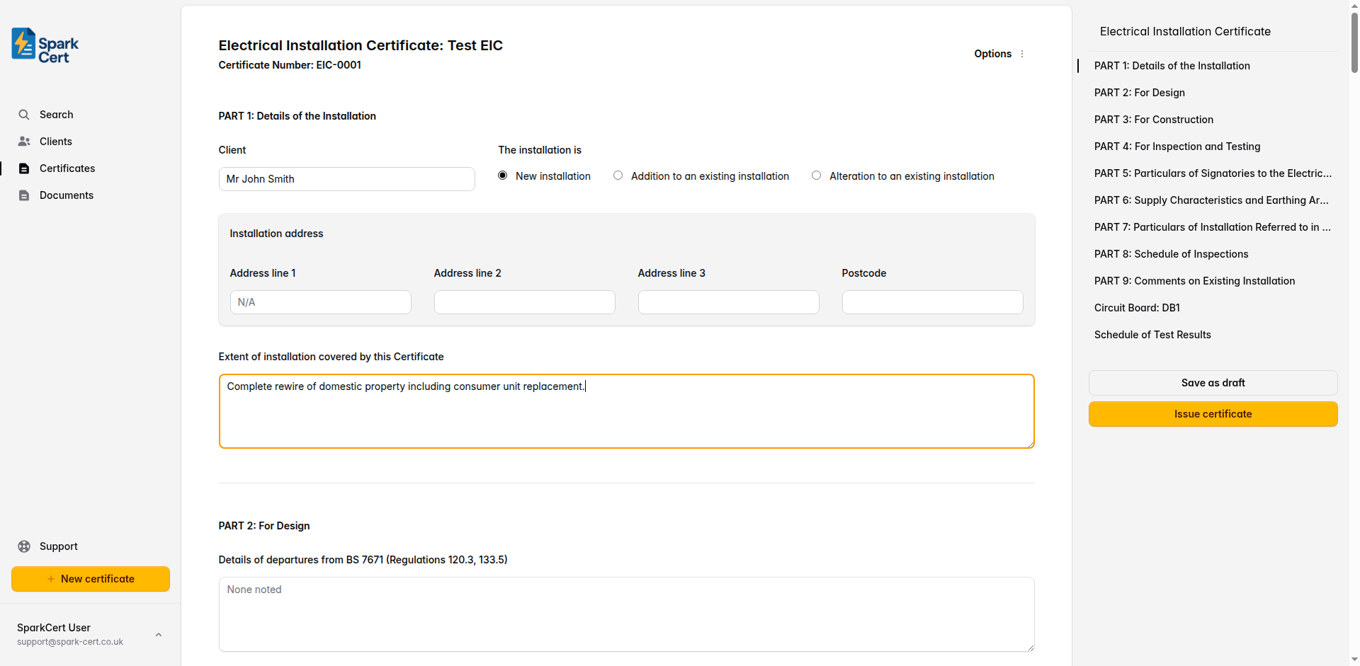
The name of the person or company the work was carried out for.
Select whether this is a new installation, an addition to an existing installation, or an alteration to an existing installation.
The full address where the work was carried out, including postcode. If you linked a client, you can select from their saved addresses or enter one manually.
Describe which parts of the installation are covered by this certificate - e.g. “Complete rewire of all ground floor and first floor lighting and ring final circuits” or “New consumer unit and all final circuits”.
Part 2 - For Design
The design section records any departures from BS 7671, permitted exceptions, and whether a risk assessment is attached. The person responsible for the design signs off here. If design responsibility is shared, a second designer can also sign.
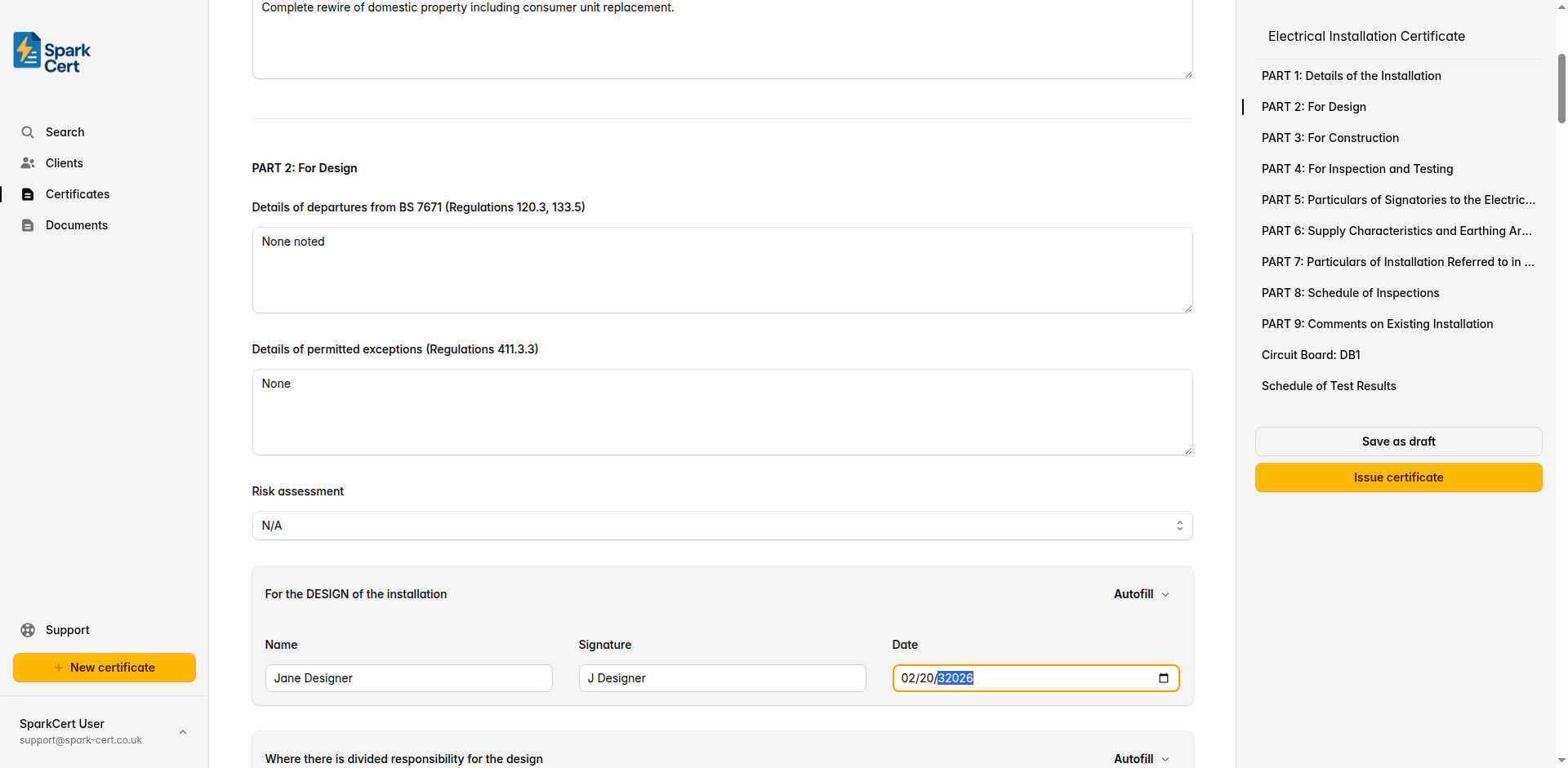
Record any departures from BS 7671 (Regulations 120.3, 133.5) and the reasons for them. Leave as “None noted” if there are none.
Record any permitted exceptions per Regulation 411.3.3. Leave as “None noted” if there are none.
Whether a risk assessment is attached. Select Yes to indicate one is attached, No if one has not been attached, or N/A if not applicable.
Designer signature (primary)
Full name of the person responsible for the design of the installation.
Typed signature for the digital certificate.
The date the design was completed.
Designer signature (divided responsibility)
If design responsibility is shared between two people, the second designer signs here. Leave blank if a single person was responsible for the entire design.
Full name of the second designer.
Typed signature for the digital certificate.
The date the design was completed.
Tip: Use the autofill button to populate the designer fields from your saved contractor details. This saves time if you are the designer, constructor, and inspector.
Part 3 - For Construction
The construction section records any departures from BS 7671 that arose during the build. The person responsible for the construction signs off to confirm the installation was built in accordance with the design.
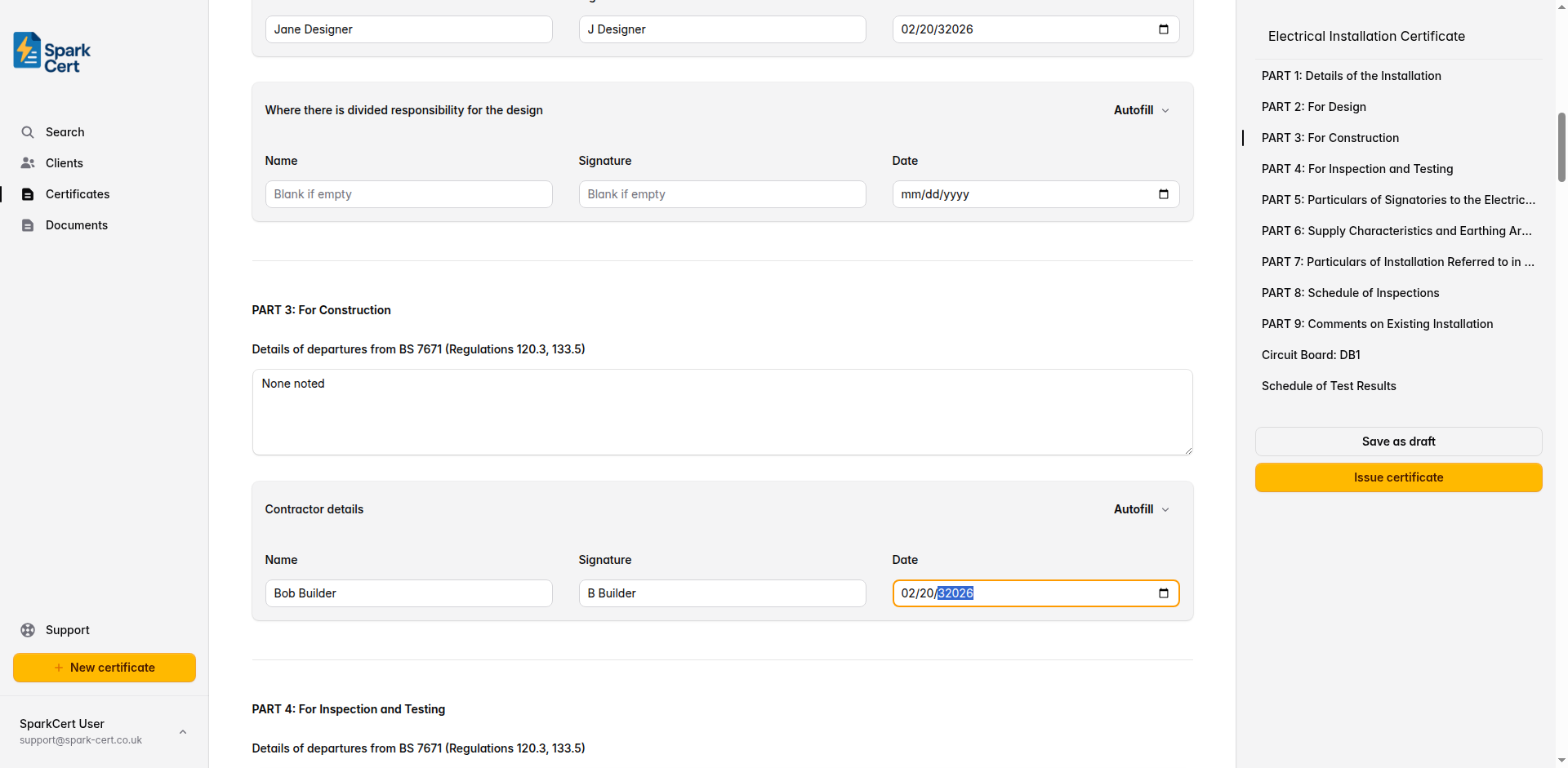
Record any departures from BS 7671 (Regulations 120.3, 133.5) that occurred during construction. Leave as “None noted” if there are none.
Full name of the person responsible for the construction of the installation.
Typed signature for the digital certificate.
The date the construction was completed.
Part 4 - For Inspection and Testing
The inspection and testing section records any departures found during the inspection process. The person who carried out the inspection and testing signs off here.
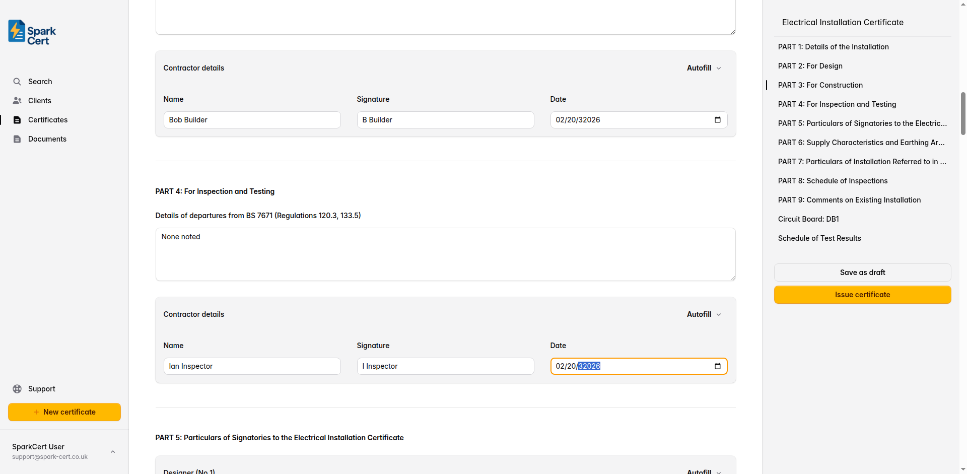
Record any departures from BS 7671 (Regulations 120.3, 133.5) found during inspection. Leave as “None noted” if there are none.
Full name of the person responsible for the inspection and testing.
Typed signature for the digital certificate.
The date the inspection and testing was carried out.
Tip: If the same person was responsible for design, construction, and inspection, use the autofill button on each section to quickly populate the details from your saved contractor profile.
Part 5 - Particulars of Signatories
This section records the full contact details for each person who signed in Parts 2, 3, and 4. There are four blocks: Designer No. 1, Designer No. 2 (if applicable), Constructor, and Inspector. Each block has the same set of fields.
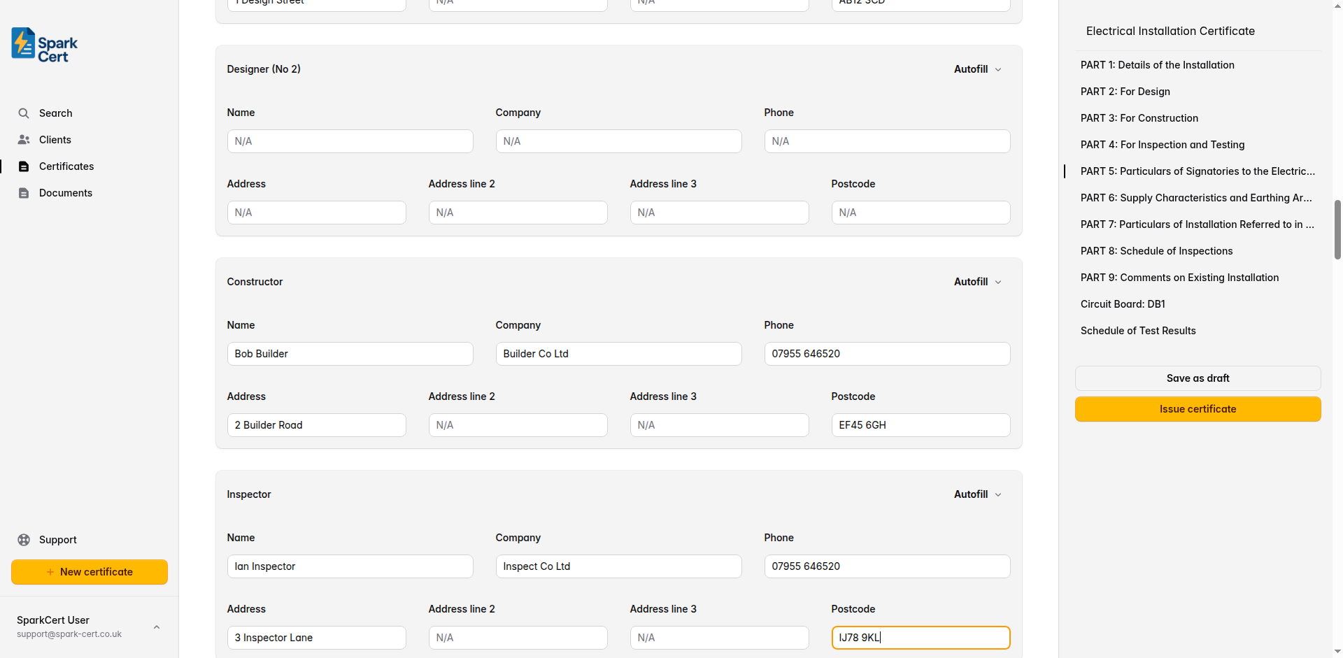
Each signatory block contains the following fields:
Full name of the signatory.
The company or trading name.
Contact telephone number.
The business address of the signatory, split across three address lines and a postcode field.
Tip: Each signatory block has an autofill button that populates the fields from your saved contractor details. If the same person fills all four roles, you can autofill each block in a single click.
Part 6 - Supply Characteristics and Earthing Arrangements
Record the characteristics of the electricity supply and the earthing system. These details should be confirmed on site before beginning the installation.
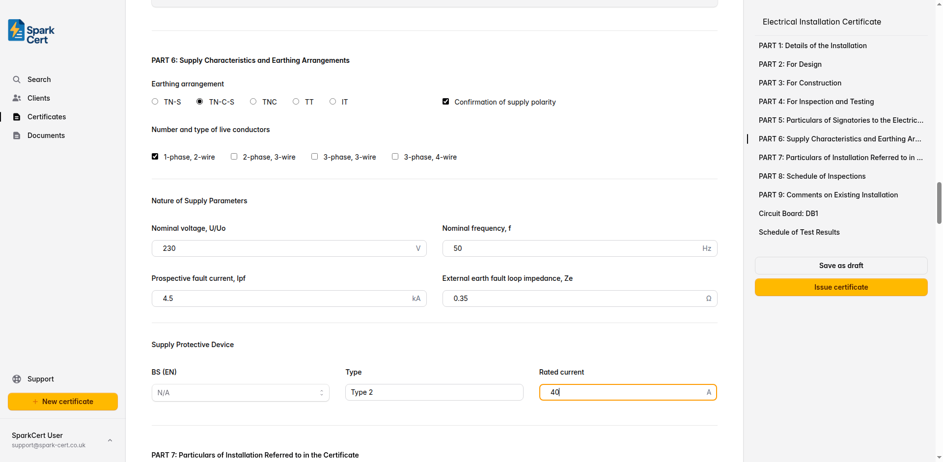
Earthing and supply configuration
Select the earthing system: TN-S, TN-C-S, TNC, TT, or IT. Check the supply intake or ask the DNO if unsure.
Tick to confirm that the supply polarity has been verified.
Select the supply configuration: 1-phase 2-wire, 2-phase 3-wire, 3-phase 3-wire, or 3-phase 4-wire. Most domestic installations are 1-phase 2-wire.
Nature of supply parameters
The nominal supply voltage - typically 230V for single-phase domestic supplies in the UK.
The nominal supply frequency - 50Hz in the UK.
The maximum prospective fault current at the origin of the installation, in kA. This must not exceed the rated short-circuit capacity of the protective devices.
The measured external earth fault loop impedance at the origin of the installation, in ohms.
Supply protective device
The standard BS (EN) number for the supply protective device. Select from common options or type a custom value.
The type of the supply protective device.
The rated current of the supply protective device in amps - e.g. “80” or “100”.
Part 7 - Particulars of Installation Referred to in the Certificate
This section captures the physical details of the installation: how it is earthed, the conductor sizes, bonding arrangements, and the main switch or circuit-breaker.
Means of earthing
Select whether earthing is provided by the distributor’s facility or an installation earth electrode.
Installation earth electrode (where applicable)
The type of earth electrode - e.g. “Rod”, “Tape”, “Plate”.
Where the earth electrode is located - e.g. “Front garden”, “Adjacent to meter cupboard”.
The measured resistance of the earth electrode in ohms.
Maximum demand and conductors
The calculated or assessed maximum demand of the installation in amps.
Earthing conductor
The material of the earthing conductor - typically copper or aluminium.
The cross-sectional area of the earthing conductor in mm².
Tick to confirm the earthing conductor connection and continuity has been verified.
Main protective bonding conductors
The material of the main protective bonding conductors.
The cross-sectional area in mm².
Tick to confirm the bonding conductor connections and continuity have been verified.
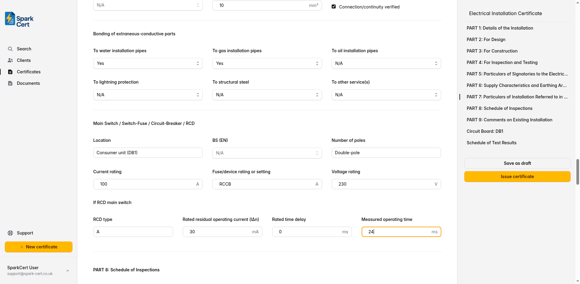
Bonding of extraneous-conductive parts
Whether main protective bonding to the water service is present.
Whether main protective bonding to the gas service is present.
Whether main protective bonding to the oil supply is present.
Whether main protective bonding to the lightning protection system is present.
Whether main protective bonding to structural steel is present.
Any other extraneous-conductive-parts that require bonding. If Yes or No is selected, a text field appears to specify what it is.
Main switch / switch-fuse / circuit-breaker / RCD
Where the main switch is located - e.g. “Hallway cupboard”, “Under stairs”.
The standard number for the main switch or circuit-breaker.
The number of poles on the main switch - typically “2” for single-phase domestic installations.
The current rating of the main switch in amps.
The fuse rating or device setting in amps.
The voltage rating of the main switch in volts.
If RCD main switch
Complete this section if the main switch is an RCD or RCBO.
The type of RCD - e.g. A, AC, B, or F.
The residual current at which the RCD trips - e.g. “30” or “100”.
The rated time delay for a time-delayed (S-type) RCD, in milliseconds. Leave blank for non-delayed types.
The actual measured operating time of the RCD when tested at rated residual current.
Part 8 - Schedule of Inspections
Work through each inspection item and mark it as satisfactory, not applicable, or requires attention. These items cover the visual inspection requirements of BS 7671, from the consumer’s intake equipment through to special locations.
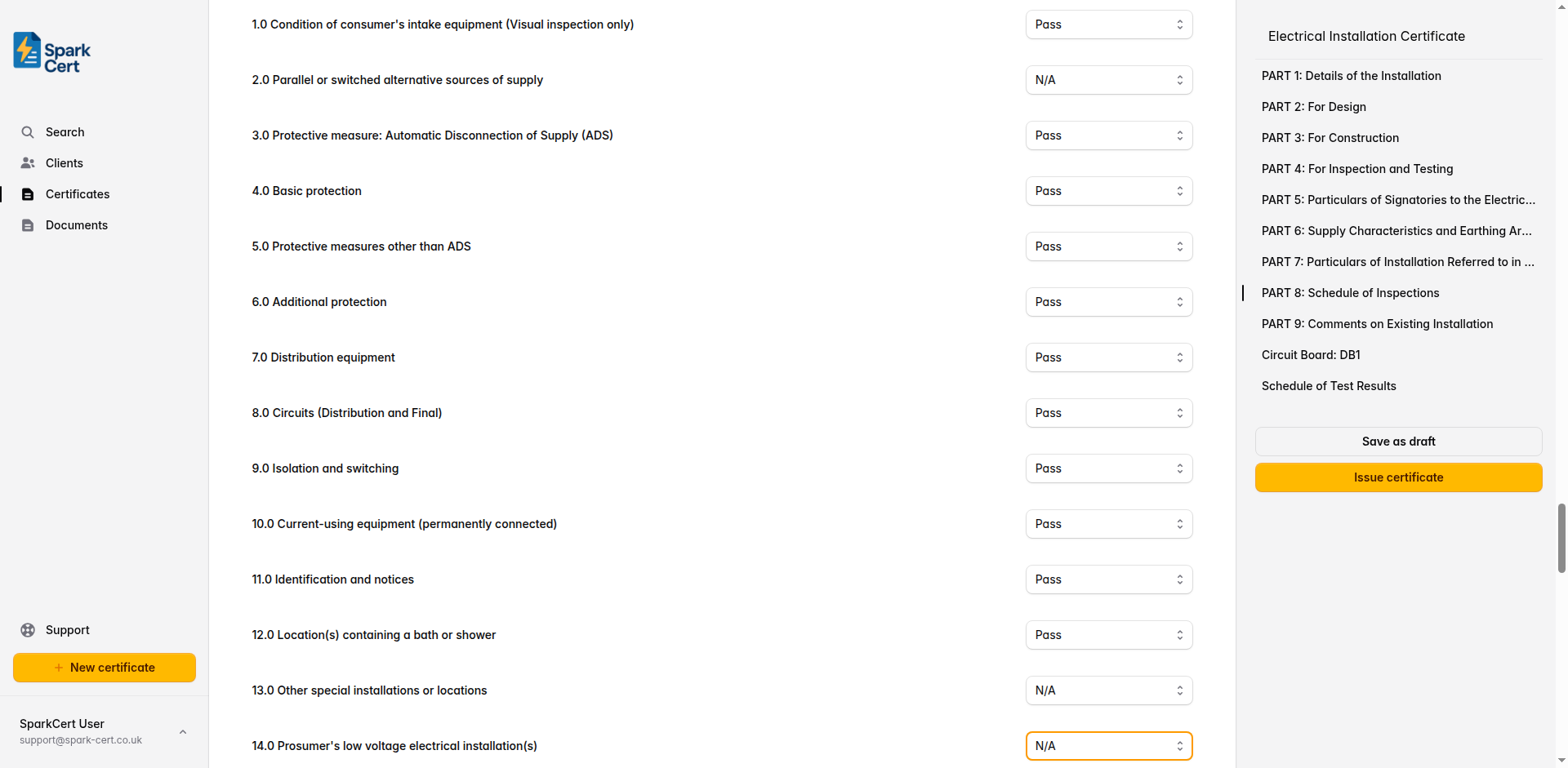
Condition of consumer’s intake equipment (visual inspection only)
Parallel or switched alternative sources of supply
Protective measure: Automatic Disconnection of Supply (ADS)
Basic protection
Protective measures other than ADS
Additional protection
Distribution equipment
Circuits (distribution and final)
Isolation and switching
Current-using equipment (permanently connected)
Identification and notices
Location(s) containing a bath or shower
Other special installations or locations
Prosumer’s low voltage electrical installation(s)
Each inspection item can be marked as satisfactory, not applicable, or requires attention. Mark items as N/A where they do not apply to the installation - for example, item 12.0 for properties without a bath or shower.
Part 9 - Comments on Existing Installation
Use this section to record any observations or recommendations about the existing installation that are relevant to the work covered by this certificate.
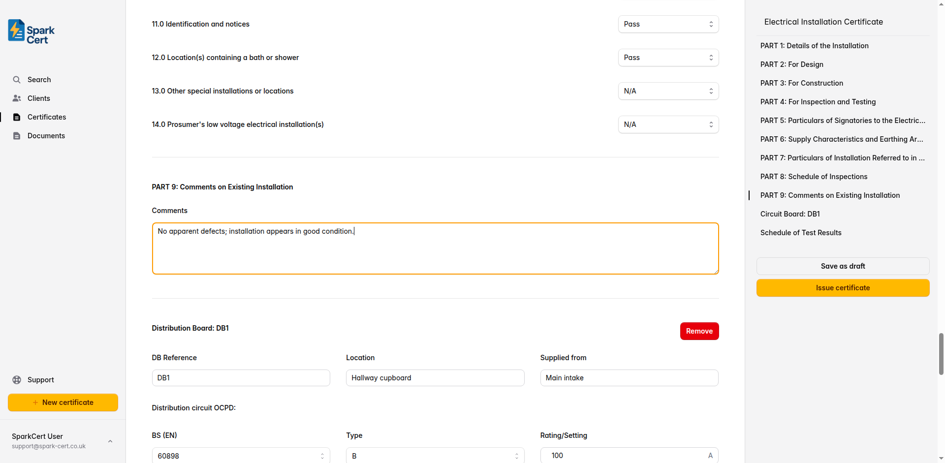
Record any observations and recommendations for the existing installation. For new installations where there is no existing installation to comment on, you can leave this as “None noted”.
Distribution boards and test results
The schedule of test results is organised by distribution board. Add a schedule for each DB in the installation, then fill in the board details, test instrument information, and circuit-level test results. Most domestic installations will have a single board, but you can add as many as needed.
Board details
The distribution board reference - auto-generated as DB1, DB2, etc. You can change this to match your own numbering.
Where the distribution board is located - e.g. “Hallway”, “Garage”.
What supplies this board - e.g. “Main intake” or the reference of another DB.
Distribution circuit overcurrent protective device (OCPD)
The standard number for the overcurrent protective device feeding this board.
The type characteristic of the OCPD - options update based on the BS (EN) selected.
The current rating or setting of the OCPD in amps.
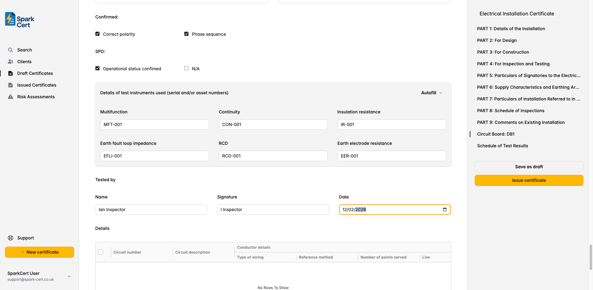
SPD, impedance, and confirmations
Select the surge protection device type: T1, T2, T3, or N/A if no SPD is fitted.
The earth fault loop impedance at the distribution board, in ohms.
The protective fault current at the distribution board, in kA.
Tick to confirm correct polarity at the distribution board.
Confirm correct phase sequence for three-phase installations. Select Yes, No, or N/A for single-phase.
Two checkboxes: tick Operational status confirmed to confirm the SPD is functioning correctly, or tick N/A if no SPD is fitted.
Test instruments
Record the serial or asset numbers of the instruments used for testing. Use the autofill button to populate these from your saved instrument details.
Serial/asset number of the multifunction tester.
Serial/asset number of the continuity tester (if separate from multifunction).
Serial/asset number of the insulation resistance tester.
Serial/asset number of the loop impedance tester.
Serial/asset number of the RCD tester.
Serial/asset number of the earth electrode resistance tester (if applicable).
Tested by
Full name of the person who carried out the testing.
Typed signature for the digital certificate.
The date the testing was carried out. Defaults to today’s date.
Circuit details table
Below the board header is a spreadsheet-style table where you enter the test results for each circuit. Add a row for every circuit in the distribution board.
Circuit identification
The circuit number or identifier as marked on the distribution board.
What the circuit supplies - e.g. “Ring final - kitchen sockets”, “Lighting - first floor”.
Conductor details
The cable or wiring system used for the circuit.
The cable installation method per BS 7671 (e.g. A, B, C, 100, 101, 102). This affects the cable’s current-carrying capacity.
How many outlets, luminaires, or connection points are on this circuit.
The cross-sectional area of the live conductors in mm².
The cross-sectional area of the circuit protective conductor in mm².
Overcurrent protective device
The standard number for the overcurrent protective device.
The type characteristic of the device - typically B, C, or D for MCBs.
The current rating of the device in amps.
The rated short-circuit breaking capacity of the device in kA.
The maximum permitted earth fault loop impedance for this protective device, in ohms.
RCD
The standard number for the RCD.
The RCD type: A, AC, B, or F.
The rated residual operating current in milliamps - typically 30mA for additional protection.
The rated current of the RCD in amps.
Continuity (Ω)
Resistance of the line conductor.
Resistance of the neutral conductor.
Resistance of the circuit protective conductor.
The measured resistance of the line conductor plus the circuit protective conductor. Used to verify Zs.
The resistance of the circuit protective conductor alone.
Insulation resistance
The voltage used for the insulation resistance test - typically 500V for circuits up to 500V.
Insulation resistance between live conductors (line to neutral). Minimum acceptable value is 1MΩ.
Insulation resistance between live conductors and earth. Minimum acceptable value is 1MΩ.
Polarity, earth fault loop impedance, RCD, and AFDD
Polarity test result - select N/A, Pass, or Fail.
The highest earth fault loop impedance measured at any point on the circuit. Must not exceed the maximum permitted Zs for the protective device fitted.
The measured disconnection time when tested at rated residual current.
Whether the RCD trips when its test button is pressed - select N/A, Pass, or Fail.
Whether the arc fault detection device trips when its test button is pressed - select N/A, Pass, or Fail.
Tip: You can add multiple distribution boards by clicking the “Add board” button in the Schedule of Test Results section. Each board gets its own header, test instruments, and circuit table.
Installation images
You can attach up to 30 photographs to the certificate. These are embedded directly into the generated PDF under an “Installation Images” section, making them a permanent part of the certificate record.
Click the upload area at the bottom of the form to select one or more images. Accepted formats are JPEG, PNG, and WebP, up to 10 MB each. Images are saved immediately - they are not part of the form’s autosave cycle.
Each image has an optional caption field. Click below a thumbnail to add a description such as “Distribution board after installation” or “Earthing arrangement at origin”. Captions appear beneath the corresponding image in the PDF.
Drag and drop images to change the order they appear in the PDF. Hover over an image and click the red cross to remove it.
Tip: For full EICs, photographs of the distribution board, earthing arrangements, and main bonding connections provide valuable evidence of the installation at the time of certification.
Issuing the certificate
Once you’ve completed all nine parts and your distribution board test results, review the certificate for accuracy and issue it. Issuing the certificate locks it to prevent accidental edits, and you can then download the PDF or email it directly to your client from SparkCert.
If you need to make corrections after issuing, you can unlock the certificate, make your changes, and re-issue it.