How to Complete a Minor Works Certificate
The Minor Electrical Installation Works Certificate is used for electrical work that does not include the provision of a new circuit. This guide walks through every section of the form so you can complete it accurately and issue it to your client.
Before you begin
A Minor Works certificate covers small-scale electrical work such as adding a socket to an existing circuit, replacing a consumer unit, or installing a new light fitting. If the work involves a new circuit, you need an Electrical Installation Certificate (EIC) instead.
The certificate is split into five parts: description of works, earthing and bonding, circuit details, test results, and declaration. You can save your progress at any time and come back later.
Getting started
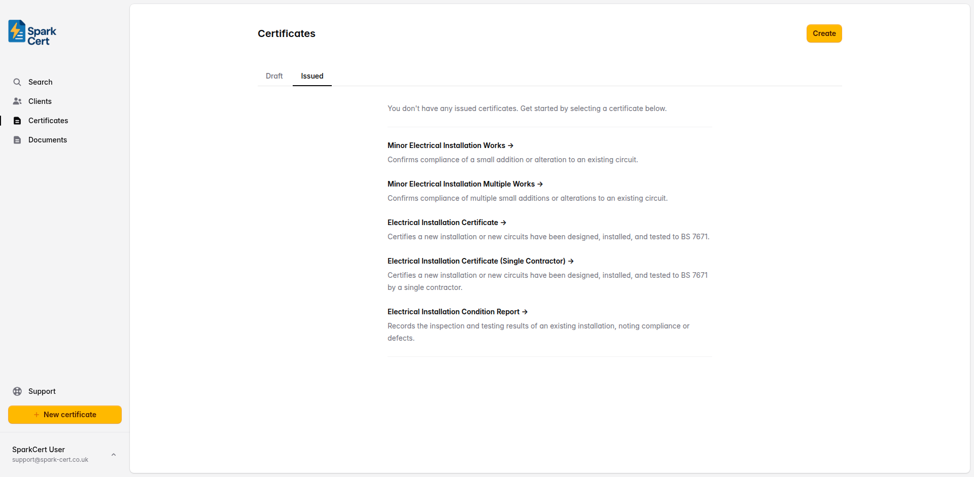
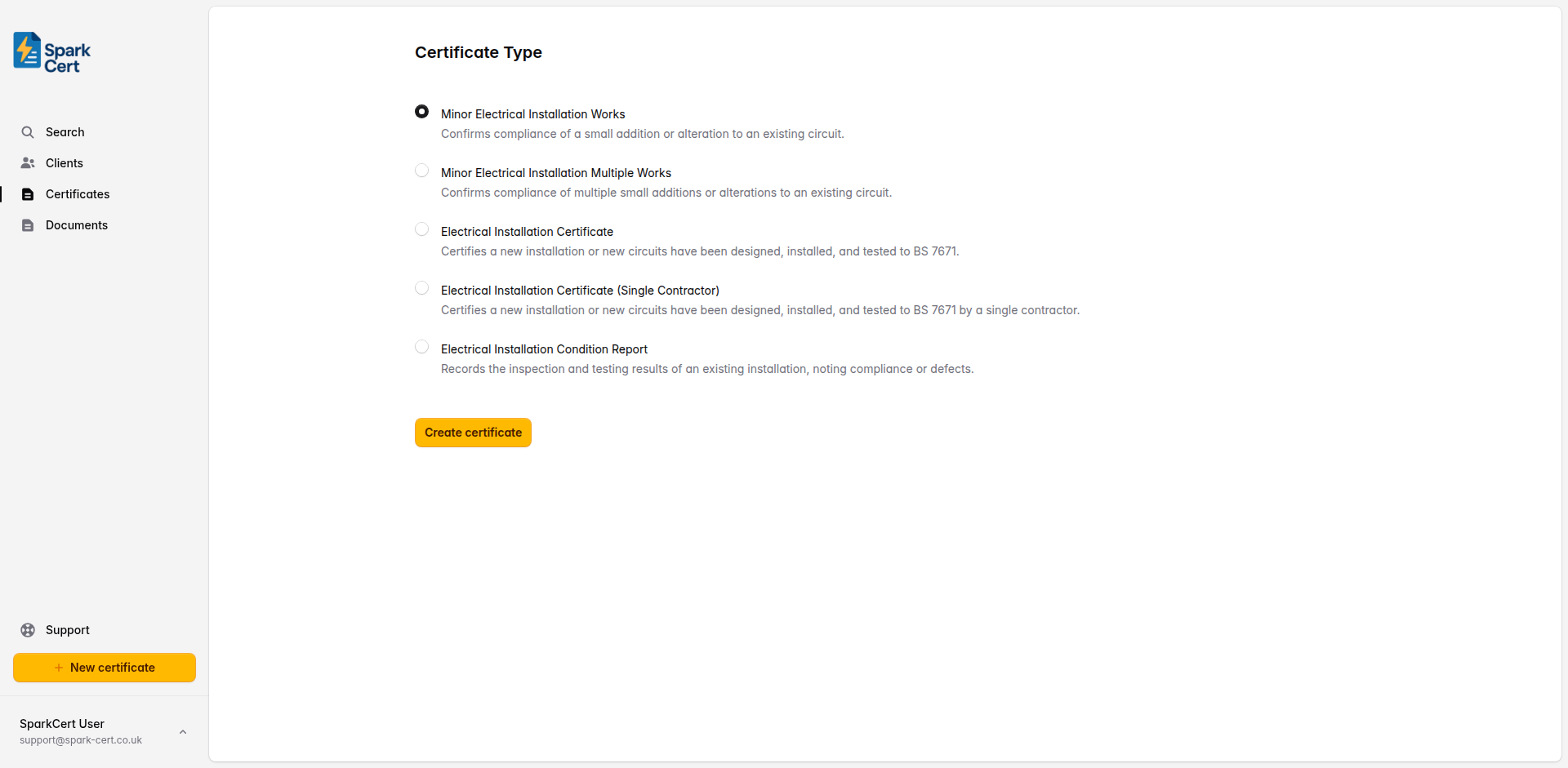
Navigate to Certificates → Create and select Minor Works as the certificate type. If you don't have any certificates yet, the type selection will appear directly on the certificates page; otherwise you'll be taken to a separate form. Choose the client and installation address for the job. If the client doesn't exist yet, you can create them inline without leaving the form.
Certificate details
After selecting the certificate type, you'll be taken to the create form. Here you set the basic details before moving on to the certificate itself.
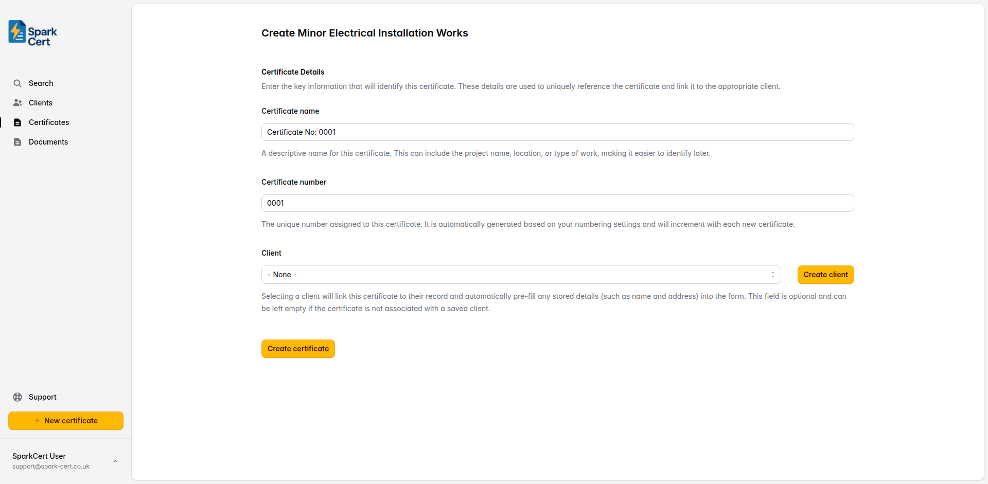
A descriptive name to help you identify the certificate later. This could be the project name, location, or type of work. A default is generated automatically, but you can change it to something more meaningful.
A unique number for the certificate. This is generated automatically based on your numbering settings and increments with each new certificate.
Optionally link the certificate to a saved client. Selecting a client will pre-fill their name and address into the form. You can also create a new client inline without leaving the page. This field can be left empty if you prefer to enter the details manually.
Linking a saved client to the certificate means it will appear on that client’s details page, making it easy to find all certificates for a particular client. If you type the client name as plain text in Part 1 instead, the certificate won’t be linked to a client record.
Part 1 - Description of the Minor Works
This section captures who the work was done for, where, and what was carried out. Provide enough detail that another electrician reading the certificate could understand the scope of the job.
The name of the person or company the work was carried out for.
The date the electrical work was finished on site.
The full address where the work was carried out, split across four fields (address line 1, line 2, line 3, and postcode). Filled automatically from the selected client address, or enter manually.
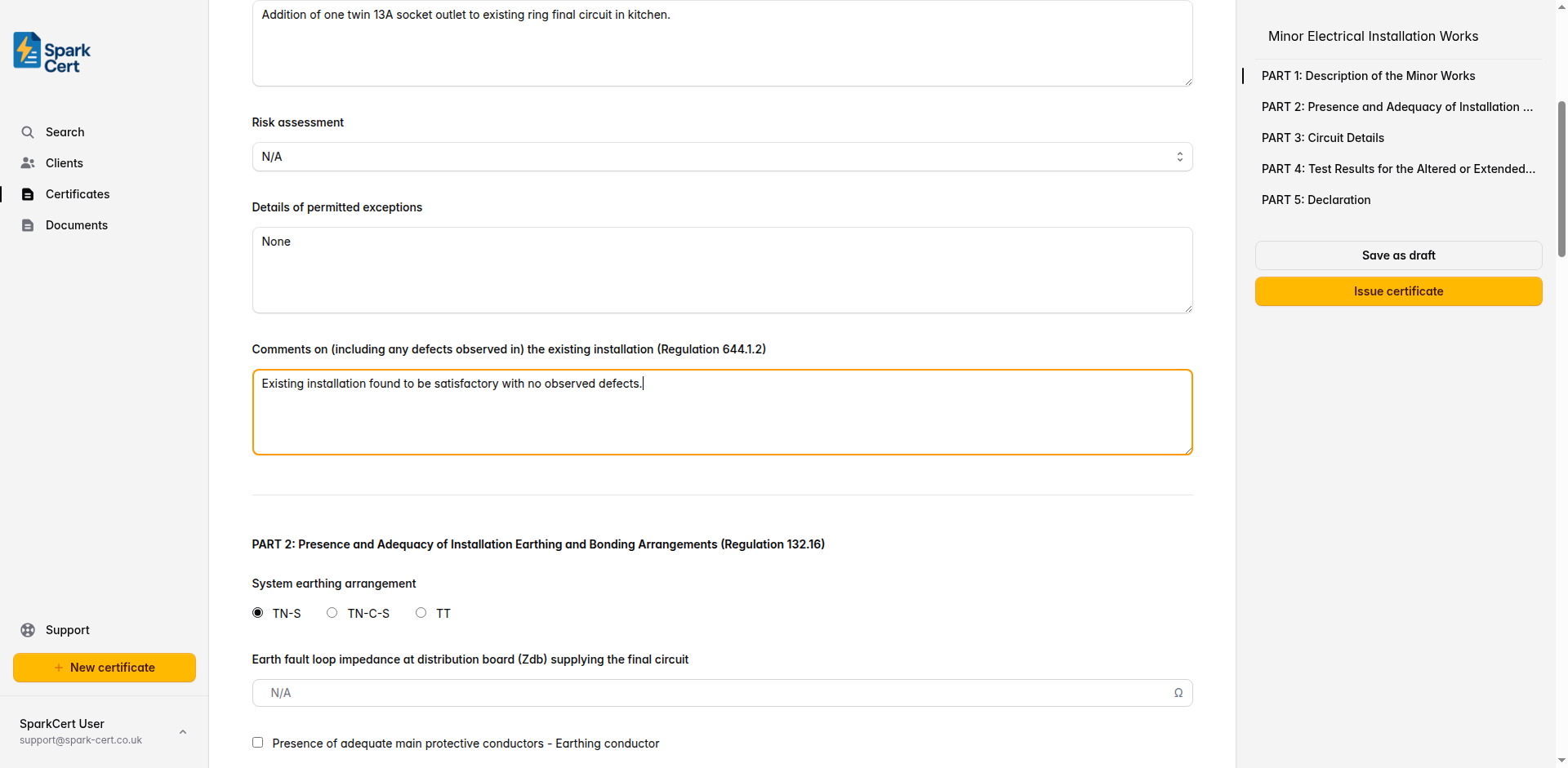
A clear description of what was done - e.g. “Addition of a double socket outlet to an existing ring final circuit in the kitchen.”
Whether a risk assessment is attached. Select Yes to indicate one is attached, No if one has not been attached, or N/A if not applicable.
Record any departures from BS 7671 and the reasons for them. Leave blank if there are none.
Note any relevant observations about the existing installation - e.g. “Existing installation in satisfactory condition.”
Tip: Be specific in the description. “Socket added” is too vague. Include the circuit affected, the location, and the type of accessory installed.
Part 2 - Earthing and Bonding Arrangements
Confirm the earthing system type and verify that adequate protective bonding is in place. This section satisfies the requirements of Regulation 132.16.
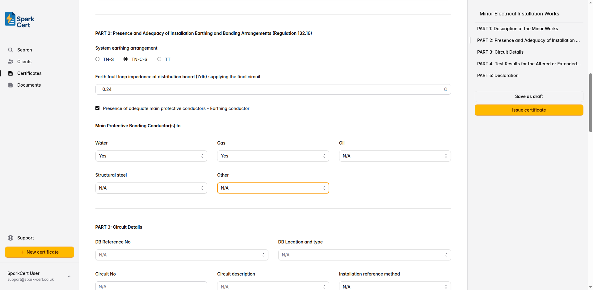
Select the earthing system: TN-S, TN-C-S, or TT. Check the supply intake or ask the DNO if unsure.
The measured earth fault loop impedance at the distribution board, in ohms. This is needed to verify disconnection times.
Tick to confirm that the main earthing conductor is present and of adequate size.
Whether main protective bonding to the water service is present.
Whether main protective bonding to the gas service is present.
Whether main protective bonding to the oil supply is present.
Whether main protective bonding to structural steel is present.
Any other extraneous-conductive-parts that require bonding. If selected, a text field appears to specify what it is.
Part 3 - Circuit Details
Record the details of the circuit you worked on, including the protective devices that protect it. This information is essential for verifying that the circuit meets the design requirements of BS 7671.
Circuit identification
The distribution board reference (e.g. DB1). Select from common options or type a custom value.
Where the distribution board is located - e.g. “Hallway”, “Garage”. Type a custom location if needed.
The circuit number as marked on the distribution board - e.g. “3” or “5”.
What the circuit supplies - e.g. “Socket outlets”, “Lighting”, “Cooker”. Select or type a custom description.
The cable installation method per BS 7671 (e.g. A, B, C, 100, 101, 102). This affects the cable’s current-carrying capacity.
The cross-sectional area of the live conductors in mm² - e.g. “2.5” for a ring final circuit.
The cross-sectional area of the circuit protective conductor - e.g. “1.5” for standard twin and earth cable.
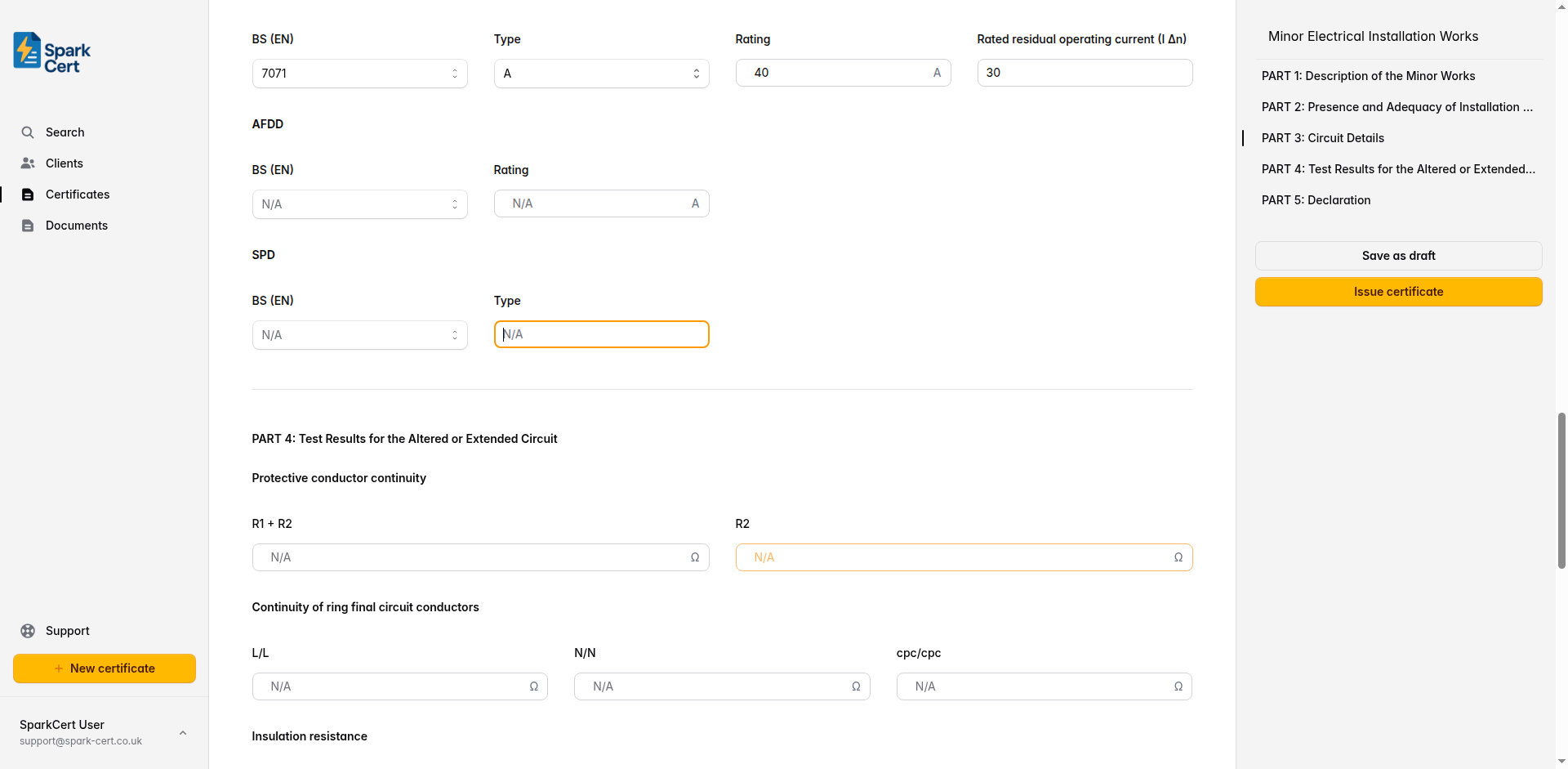
Overcurrent protective device
The British or European Standard number for the overcurrent protective device - e.g. “BS EN 60898”.
The type characteristic of the device - typically B, C, or D for MCBs.
The current rating in amps - e.g. “32” for a ring final circuit or “6” for lighting.
RCD details
The standard number for the RCD - e.g. “BS EN 61008” or “BS EN 61009”.
The RCD type: A, AC, B, or F. Most domestic installations use Type A or AC.
The rated current of the RCD in amps.
The residual current at which the RCD trips - typically 30mA for additional protection.
AFDD and SPD details
The standard number for the arc fault detection device, if fitted.
The rated current of the AFDD in amps.
The standard number for the surge protection device, if fitted.
The type of SPD installed - Type 1, 2, or 3.
Part 4 - Test Results
Enter the test results for the circuit you altered or extended. All tests should be carried out in accordance with BS 7671 and the IET Guidance Note 3. Record actual measured values - not calculated or estimated ones.
Continuity
The measured resistance of the line conductor plus the circuit protective conductor. Used to verify Zs.
The resistance of the circuit protective conductor alone.
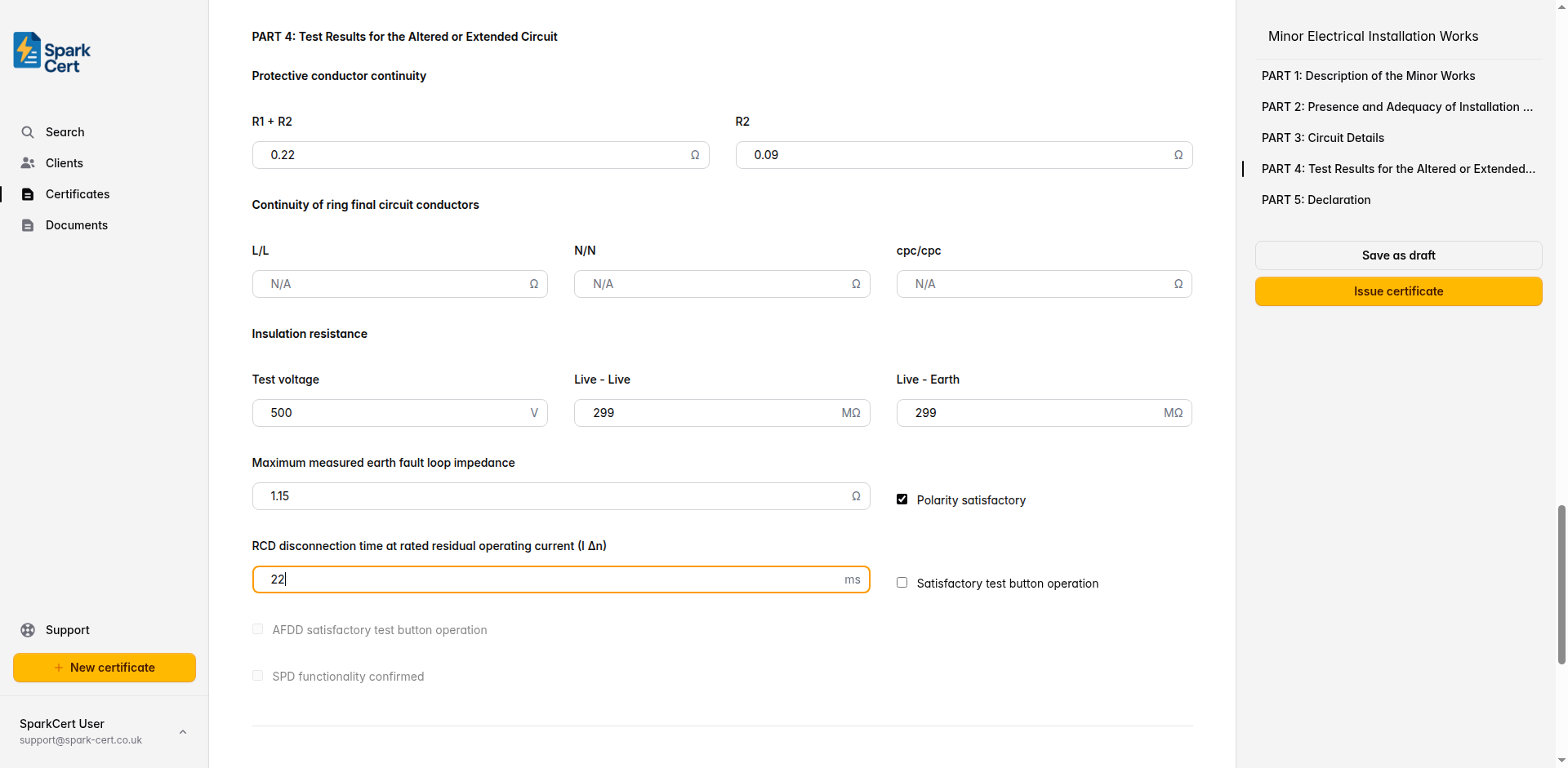
Line-to-line end-to-end resistance for ring final circuits. Leave blank for radial circuits.
Neutral-to-neutral end-to-end resistance for ring final circuits.
CPC-to-CPC end-to-end resistance for ring final circuits.
Insulation resistance
The voltage used for the insulation resistance test - typically 500V for circuits up to 500V.
Insulation resistance between live conductors (line to neutral). Minimum acceptable value is 1MΩ.
Insulation resistance between live conductors and earth. Minimum acceptable value is 1MΩ.
Earth fault loop impedance, polarity, and RCD
The highest earth fault loop impedance measured at any point on the circuit. Must not exceed the value in BS 7671 Table 41.2–41.4 for the protective device fitted.
Tick to confirm that correct polarity has been verified at the origin and at each point in the circuit.
The measured disconnection time when tested at rated residual current. Must be ≤ 300ms (or ≤ 40ms for additional protection at 5× IΔn).
Tick to confirm the RCD trips when its test button is pressed. Only enabled if an RCD is specified in Part 3.
Tick to confirm the AFDD trips when its test button is pressed. Only enabled if an AFDD is specified in Part 3.
Tick to confirm the SPD is functioning correctly. Only enabled if an SPD is specified in Part 3.
Tip: If you’re working on a radial circuit, leave the ring continuity fields blank. SparkCert won’t flag them as missing.
Part 5 - Declaration
The declaration confirms that the work complies with BS 7671 (as amended) and that the installation has been designed, constructed, inspected, and tested in accordance with the standard. This is a legal statement - ensure all details are correct before signing.
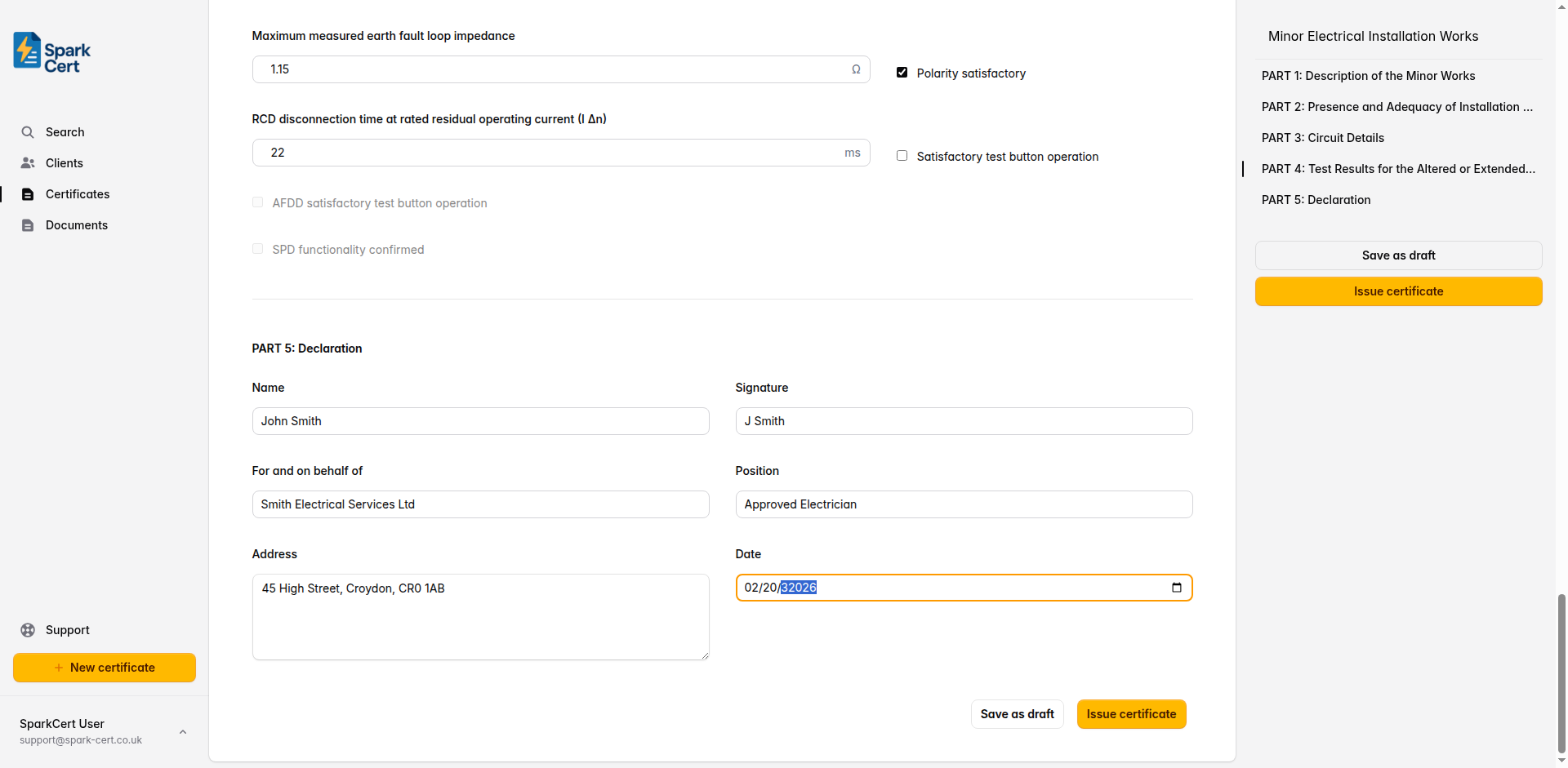
Your full name as the person responsible for the work.
Your typed signature for the digital certificate.
The company or trading name you are signing on behalf of.
Your role within the company - e.g. “Director”, “Qualified Supervisor”.
The business address of the contractor or company.
The date the certificate is being signed and issued.
Tip: You can fill in these details once in your Profile settings. SparkCert will then pre-fill them automatically on every new certificate, so you don’t have to type them out each time.
Installation images
You can attach up to 30 photographs to the certificate. These are embedded directly into the generated PDF under an “Installation Images” section, making them a permanent part of the certificate record.
Click the upload area at the bottom of the form to select one or more images. Accepted formats are JPEG, PNG, and WebP, up to 10 MB each. Images are saved immediately - they are not part of the form’s autosave cycle.
Each image has an optional caption field. Click below a thumbnail to add a description such as “Consumer unit before works” or “New socket outlet installed”. Captions appear beneath the corresponding image in the PDF.
Drag and drop images to change the order they appear in the PDF. Hover over an image and click the red cross to remove it.
Tip: Before and after photos are especially useful for minor works - they give clients a clear visual record of what was done and provide evidence in case of disputes.
Issuing the certificate
Once you’ve completed all five parts, review the certificate for accuracy and issue it. Issuing the certificate locks it to prevent accidental edits, and you can then download the PDF or email it directly to your client from SparkCert.
If you need to make corrections after issuing, you can unlock the certificate, make your changes, and re-issue it.