How to Complete an EICR
The Electrical Installation Condition Report (EICR) is used to record the condition of an existing electrical installation. It covers inspection, testing, and the classification of any defects found. This guide walks through every section of the form so you can complete it accurately and issue it to your client.
Before you begin
An EICR is used to assess the safety of an existing electrical installation. It is not used for new installations or additions - those require an Electrical Installation Certificate (EIC) or Minor Works certificate. The EICR records the condition of the installation, identifies any defects, and classifies them using observation codes (C1, C2, C3, FI).
The certificate is split into eight numbered parts, plus a condition report inspection schedule, distribution board test results, and a final declaration. You can save your progress at any time and come back later.
Getting started
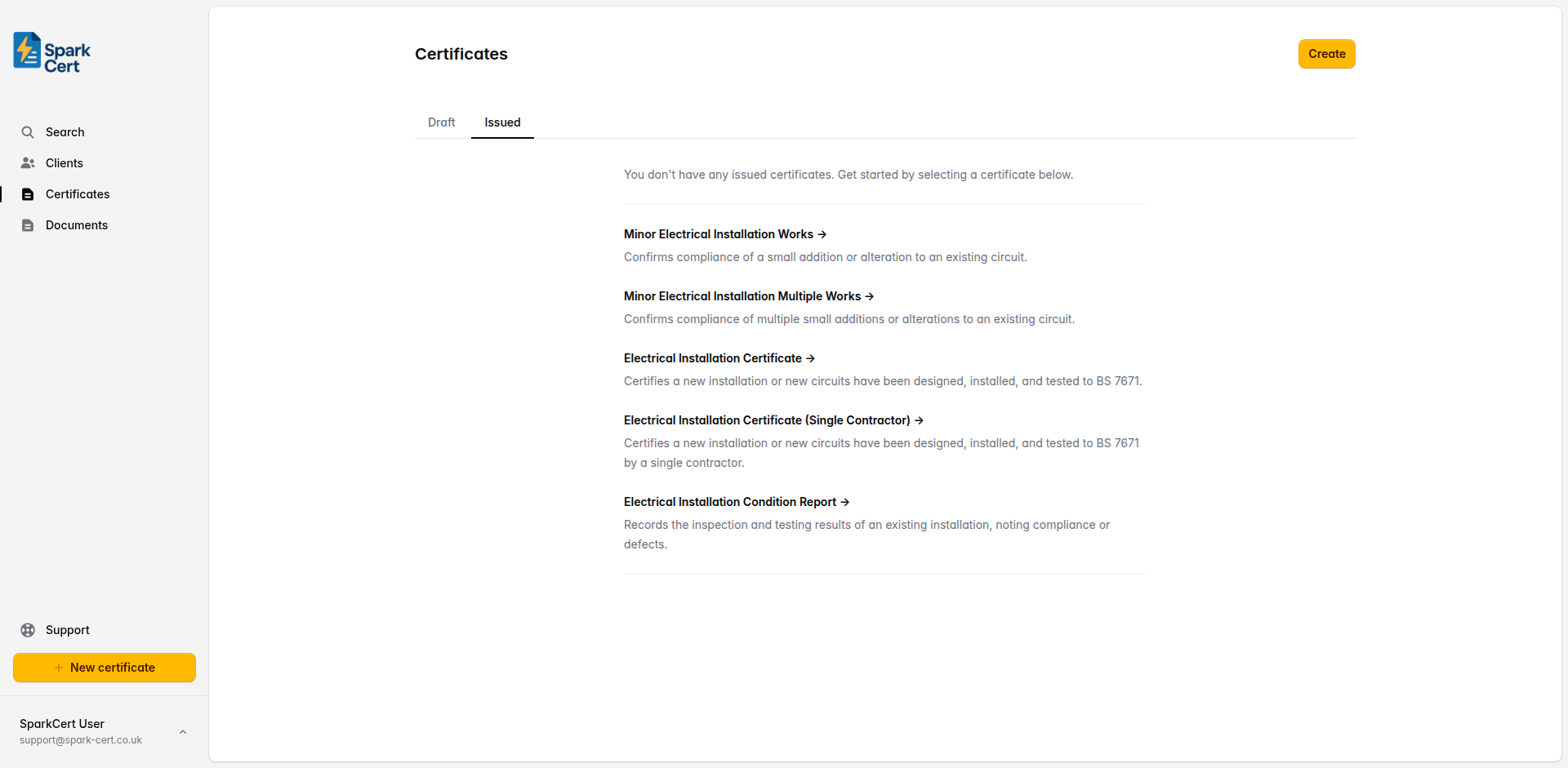
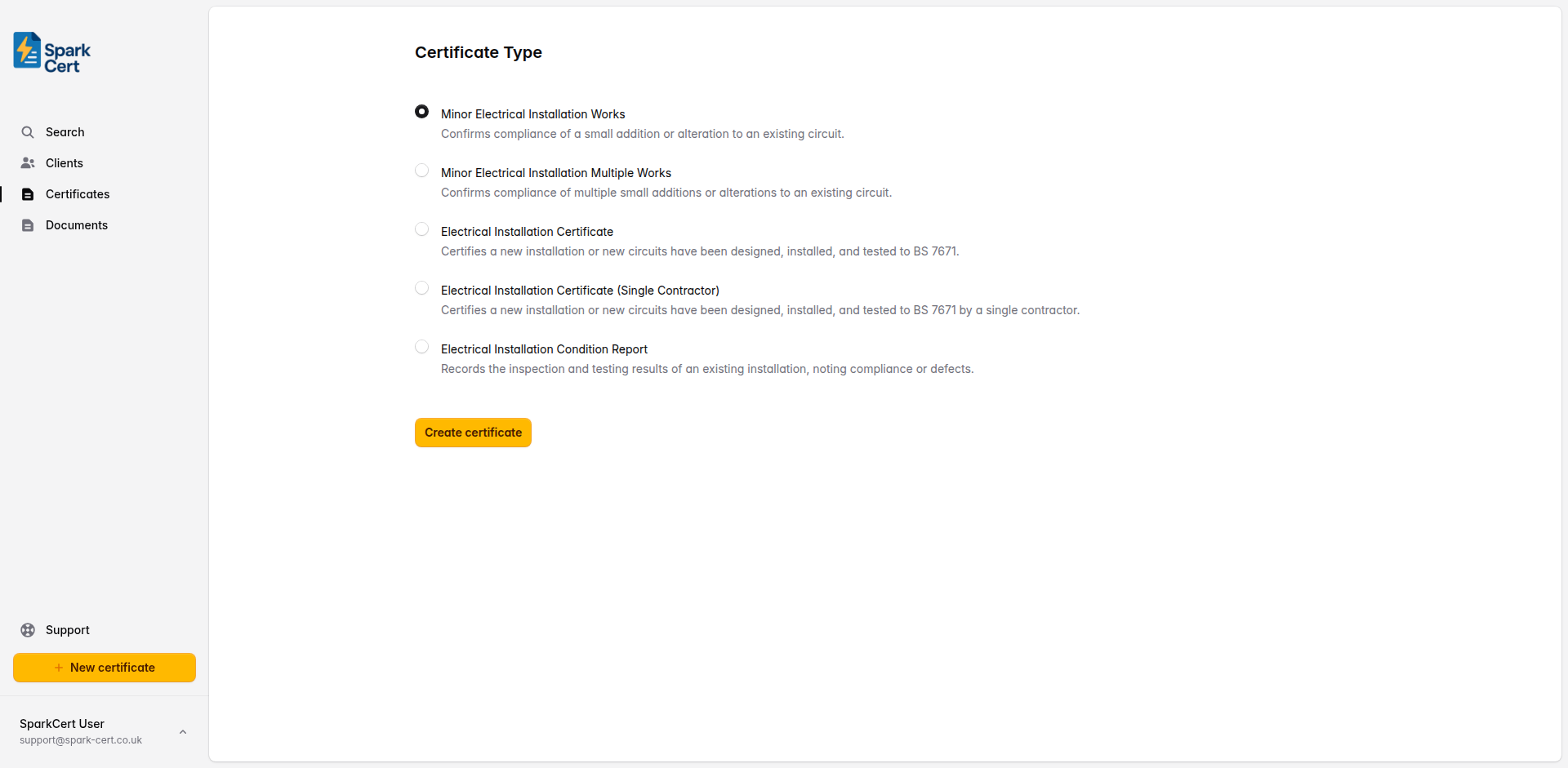
Navigate to Certificates → Create and select EICR as the certificate type. If you don't have any certificates yet, the type selection will appear directly on the certificates page; otherwise you'll be taken to a separate form. Choose the client and installation address for the inspection. If the client doesn't exist yet, you can create them inline without leaving the form.
Certificate details
After selecting the certificate type, you'll be taken to the create form. Here you set the basic details before moving on to the certificate itself.
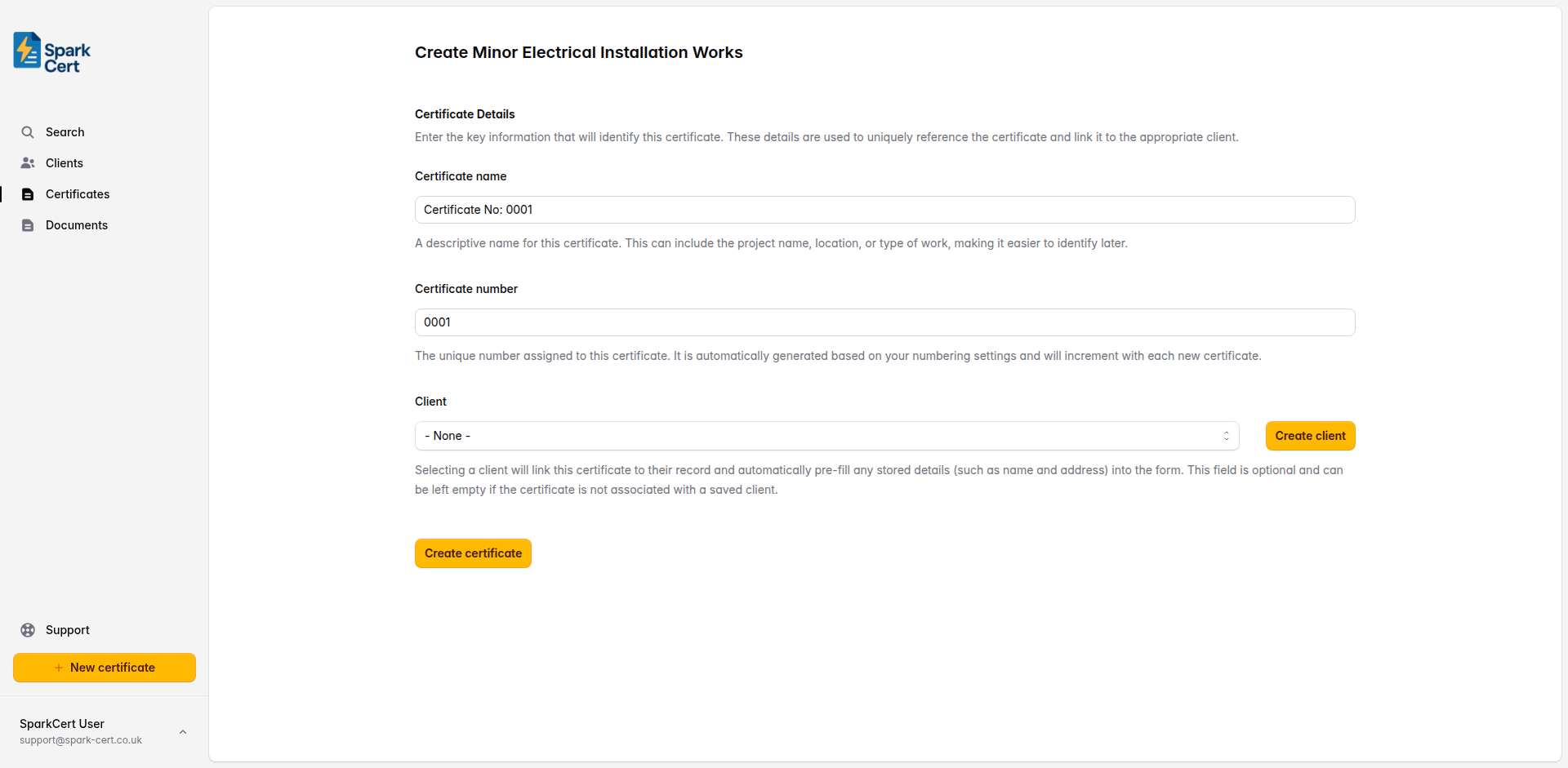
A descriptive name to help you identify the certificate later. This could be the property address, client name, or type of inspection. A default is generated automatically, but you can change it to something more meaningful.
A unique number for the certificate. This is generated automatically based on your numbering settings and increments with each new certificate.
Optionally link the certificate to a saved client. Selecting a client will pre-fill their name and address into the form. You can also create a new client inline without leaving the page. This field can be left empty if you prefer to enter the details manually.
Linking a saved client to the certificate means it will appear on that client's details page, making it easy to find all certificates for a particular client. If you type the client name as plain text in Part 1 instead, the certificate won't be linked to a client record.
Part 1 - Description of the Report
This section captures who requested the report, the occupier, the installation address, and key details about the premises and its wiring history. It provides the context needed to understand the scope and background of the inspection.
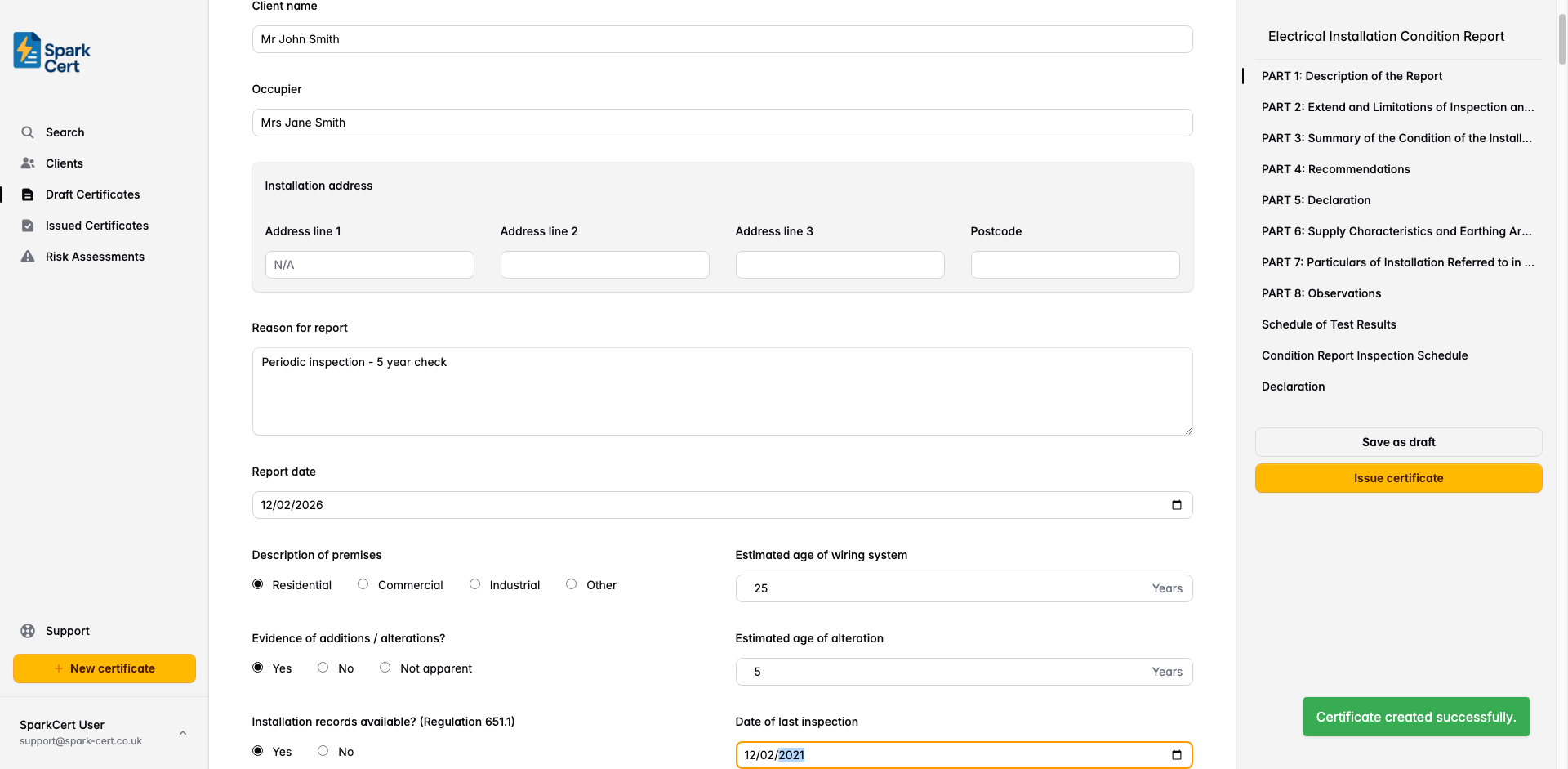
The name of the person or company who requested the condition report.
The name of the person or organisation occupying the premises. This may be different from the client - for example, if a landlord commissions the report but a tenant occupies the property.
The full address of the premises being inspected, including postcode. If you linked a client, you can select from their saved addresses or enter one manually.
Why the condition report was requested - e.g. "Periodic inspection", "Change of tenancy", "Insurance requirement", "Mortgage survey".
The date the inspection and testing was carried out.
Select the premises type: Domestic, Commercial, Industrial, or Other.
An estimate of how old the wiring system is, in years. This can be determined from cable types, accessory styles, and any available records.
Select Yes, No, or Not apparent to indicate whether there is evidence of previous additions or alterations to the installation.
If additions or alterations are evident, estimate their age in years.
Whether previous certificates, test results, or other records were available at the time of the inspection. Select Yes or No.
The date of the most recent previous inspection, if known. Leave blank if no previous records are available.
Tip: The client and occupier fields are separate because the person commissioning the report (e.g. a landlord or property manager) is often different from the person living or working at the premises.
Part 2 - Extent and Limitations of Inspection and Testing
This section records what was covered by the inspection, any agreed limitations (parts of the installation that were excluded by agreement with the client), and any operational limitations that prevented full inspection or testing.
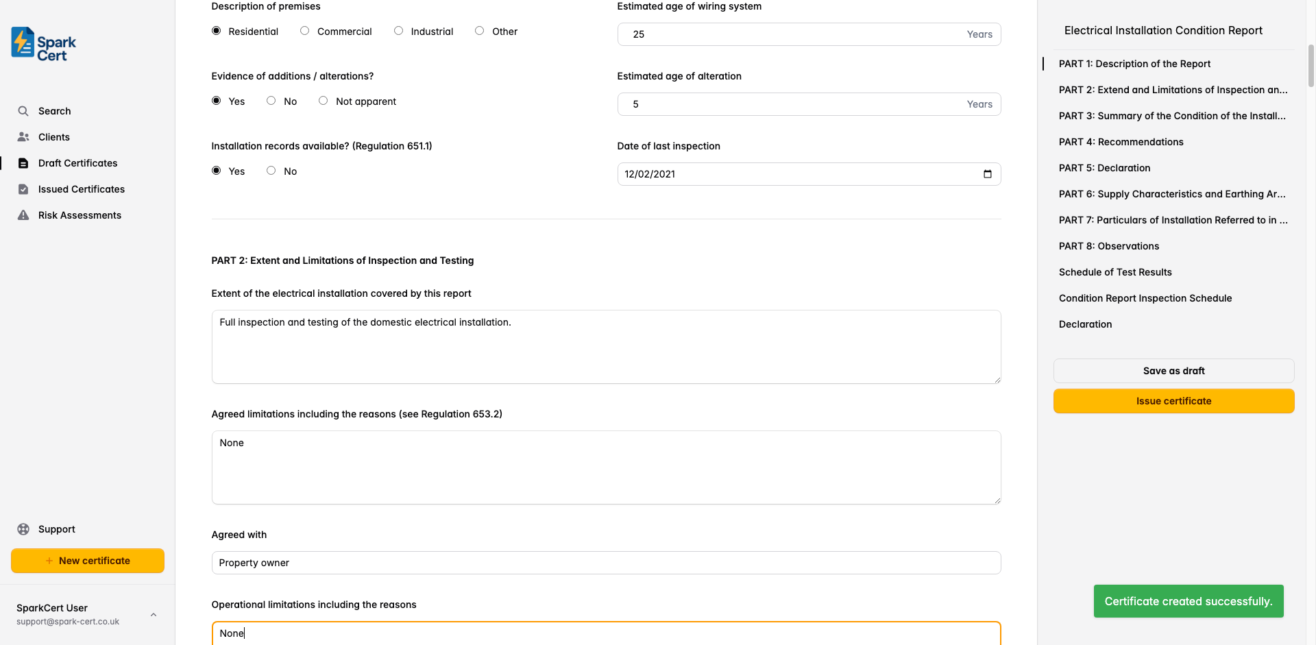
Describe which parts of the installation were inspected and tested - e.g. "The whole of the electrical installation" or "Ground floor only, excluding the garage outbuilding".
Any parts of the installation excluded by agreement with the client, and the reasons - e.g. "Loft wiring not inspected due to limited access, agreed with client prior to inspection".
The name of the person the limitations were agreed with - typically the client or their representative.
Any parts of the installation that could not be inspected or tested for practical reasons - e.g. "Unable to isolate circuits to kitchen due to occupier requiring continuous supply to fridge/freezer" or "Consumer unit locked, key not available on site".
Tip: Agreed limitations are exclusions discussed and agreed before or during the inspection. Operational limitations are restrictions discovered on site that prevented full inspection, such as locked rooms, furniture blocking access, or circuits that could not be isolated.
Part 3 - Summary of the Condition of the Installation
This section provides an overall summary of the installation's condition and the final satisfactory/unsatisfactory assessment.
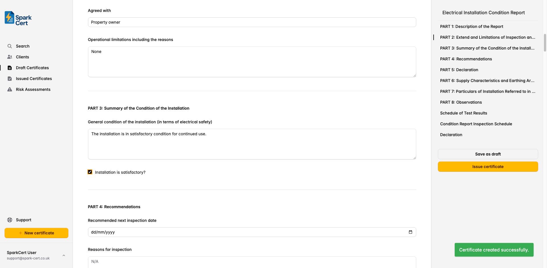
A written summary of the general condition of the installation in terms of electrical safety. This should reflect the overall findings from the inspection and testing - e.g. "The installation is generally in a satisfactory condition" or "The installation requires remedial work to address the issues identified in the observations".
Tick this box if the overall condition of the installation is satisfactory. Leave unchecked if any C1 or C2 coded observations have been recorded, as these indicate the installation is unsatisfactory.
Tip: An installation with any C1 (danger present) or C2 (potentially dangerous) observations should be marked as unsatisfactory. An installation with only C3 (improvement recommended) or FI (further investigation) observations may still be considered satisfactory, depending on your professional judgement.
Part 4 - Recommendations
This section records when the next periodic inspection should take place and the reasoning behind that recommendation.
The date by which the next periodic inspection should be carried out. Typical intervals are 5 years for domestic properties, 5 years for commercial, and 3 years for industrial. Rented properties may require more frequent inspections under local regulations.
The reasoning behind the recommended interval - e.g. "Standard 5-year periodic inspection for domestic property" or "3-year interval recommended due to age and condition of the installation".
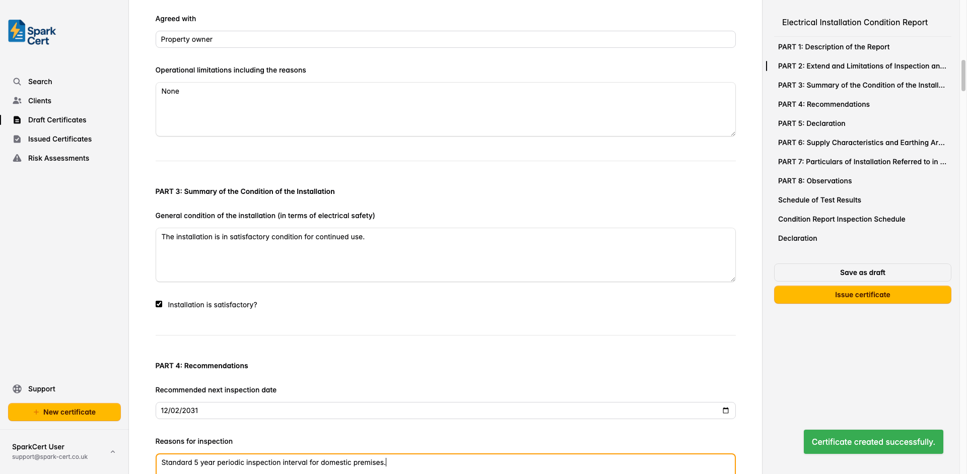
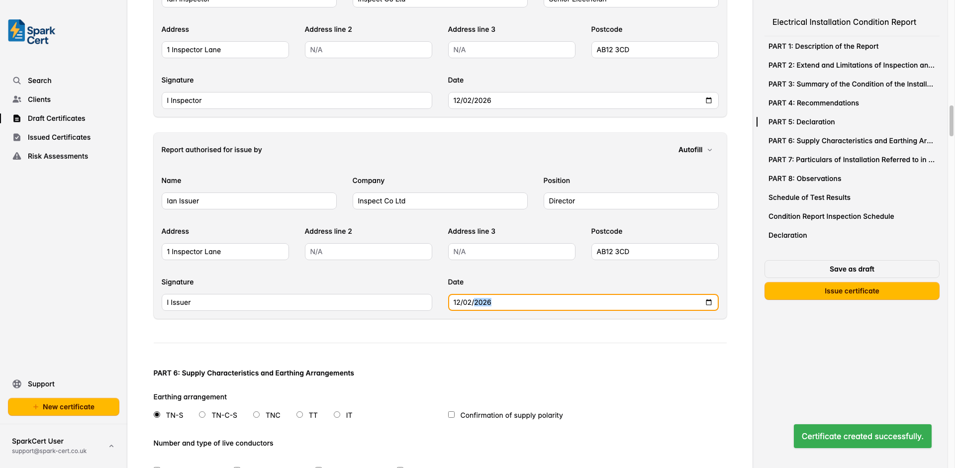
Part 5 - Declaration
The declaration section has two sign-off blocks: one for the person who carried out the inspection and testing, and one for the person authorising the report for issue. Both blocks require full contractor details. In practice, these are often the same person.
Inspected and tested by
Full name of the person who carried out the inspection and testing.
The company or trading name of the inspector.
The inspector's position or job title - e.g. "Electrician", "Qualified Supervisor", "Director".
The business address of the inspector, split across three address lines and a postcode field.
Typed signature for the digital certificate.
The date the inspection and testing was completed.
Report authorised for issue by
The person authorising the report for issue. This may be the same person who carried out the inspection, or a supervisor or manager who reviews and approves the report.
Full name of the person authorising the report.
The company or trading name.
The issuer's position or job title.
The business address of the issuer, split across three address lines and a postcode field.
Typed signature for the digital certificate.
The date the report was authorised for issue.
Tip: Use the autofill button to populate the contractor fields from your saved contractor details. If you are both the inspector and the issuer, you can autofill both blocks with a single click each.
Part 6 - Supply Characteristics and Earthing Arrangements
Record the characteristics of the electricity supply and the earthing system. These details should be confirmed on site during the inspection.
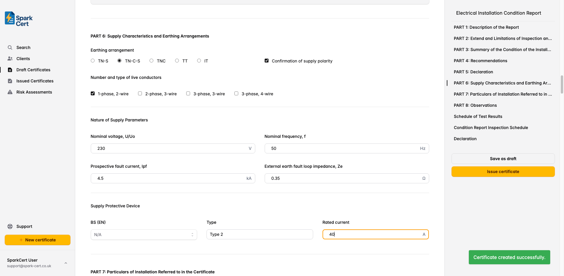
Earthing and supply configuration
Select the earthing system: TN-S, TN-C-S, TNC, TT, or IT. Check the supply intake or ask the DNO if unsure.
Tick to confirm that the supply polarity has been verified.
Select the supply configuration: 1-phase 2-wire, 2-phase 3-wire, 3-phase 3-wire, or 3-phase 4-wire. Most domestic installations are 1-phase 2-wire.
Nature of supply parameters
The nominal supply voltage - typically 230V for single-phase domestic supplies in the UK.
The nominal supply frequency - 50Hz in the UK.
The maximum prospective fault current at the origin of the installation, in kA. This must not exceed the rated short-circuit capacity of the protective devices.
The measured external earth fault loop impedance at the origin of the installation, in ohms.
Supply protective device
The standard BS (EN) number for the supply protective device. Select from common options or type a custom value.
The type of the supply protective device.
The rated current of the supply protective device in amps - e.g. "80" or "100".
Part 7 - Particulars of Installation Referred to in the Report
This section captures the physical details of the installation: how it is earthed, the conductor sizes, bonding arrangements, and the main switch or circuit-breaker.
Means of earthing
Select whether earthing is provided by the distributor's facility or an installation earth electrode.
Installation earth electrode (where applicable)
The type of earth electrode - e.g. "Rod", "Tape", "Plate".
Where the earth electrode is located - e.g. "Front garden", "Adjacent to meter cupboard".
The measured resistance of the earth electrode in ohms.
Maximum demand and conductors
The calculated or assessed maximum demand of the installation in amps.
Earthing conductor
The material of the earthing conductor - typically copper or aluminium.
The cross-sectional area of the earthing conductor in mm².
Tick to confirm the earthing conductor connection and continuity has been verified.
Main protective bonding conductors
The material of the main protective bonding conductors.
The cross-sectional area in mm².
Tick to confirm the bonding conductor connections and continuity have been verified.
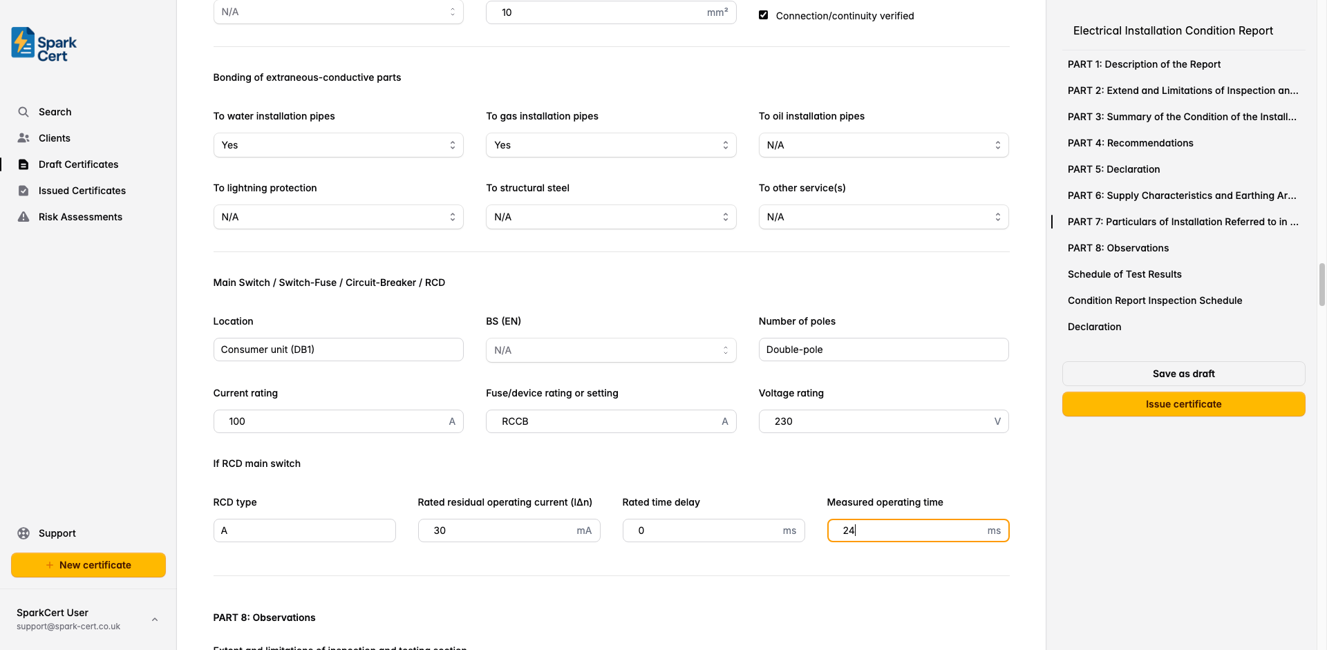
Bonding of extraneous-conductive parts
Whether main protective bonding to the water service is present.
Whether main protective bonding to the gas service is present.
Whether main protective bonding to the oil supply is present.
Whether main protective bonding to the lightning protection system is present.
Whether main protective bonding to structural steel is present.
Any other extraneous-conductive-parts that require bonding. If Yes or No is selected, a text field appears to specify what it is.
Main switch / switch-fuse / circuit-breaker / RCD
Where the main switch is located - e.g. "Hallway cupboard", "Under stairs".
The standard number for the main switch or circuit-breaker.
The number of poles on the main switch - typically "2" for single-phase domestic installations.
The current rating of the main switch in amps.
The fuse rating or device setting in amps.
The voltage rating of the main switch in volts.
If RCD main switch
Complete this section if the main switch is an RCD or RCBO.
The type of RCD - e.g. A, AC, B, or F.
The residual current at which the RCD trips - e.g. "30" or "100".
The rated time delay for a time-delayed (S-type) RCD, in milliseconds. Leave blank for non-delayed types.
The actual measured operating time of the RCD when tested at rated residual current.
Part 8 - Observations
This section records any defects or issues found during the inspection. Each observation is assigned a classification code to indicate its severity. The observations determine whether the overall installation is satisfactory or unsatisfactory.
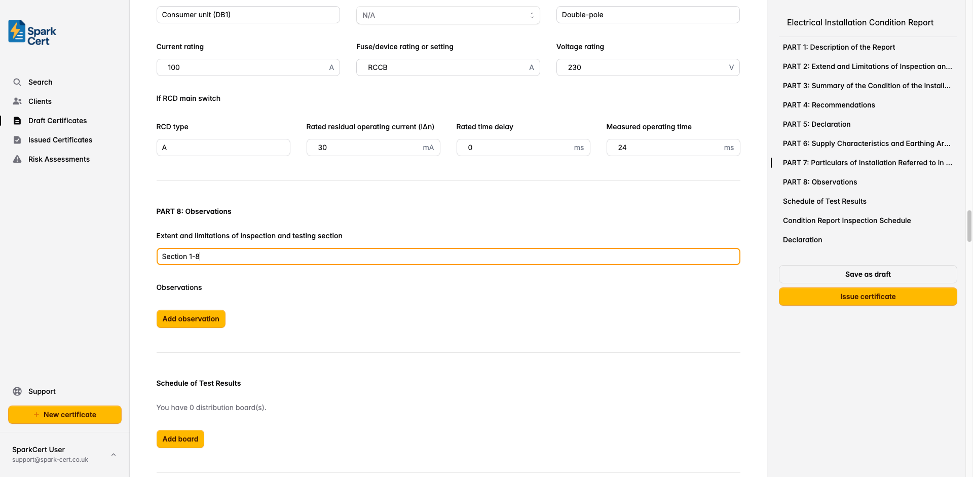
A reference to the section of the report covering the extent and limitations. This links the observations to the scope defined in Part 2.
Add one entry for each defect or observation found during the inspection. Each entry includes a description of the issue and a classification code.
Classification codes
Risk of injury. Immediate remedial action required.
Urgent remedial action required.
Improvement is recommended but the issue does not represent immediate danger.
Further investigation is required without delay to determine the extent and nature of the defect.
Tip: Be specific in your observation descriptions. Include the location, the nature of the defect, and the relevant BS 7671 regulation where applicable - e.g. "Missing earth connection at socket outlet in bedroom 2 (Reg. 411.3.1.1)".
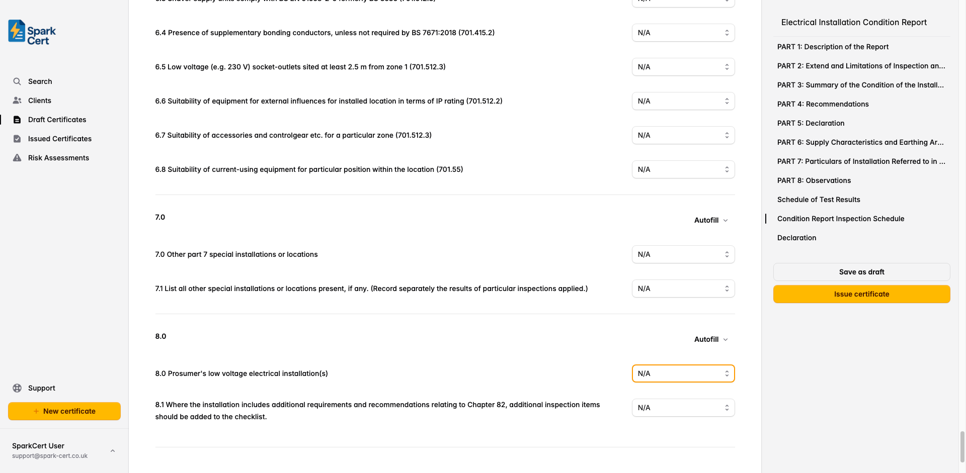
Condition Report Inspection Schedule
The inspection schedule is a comprehensive checklist of visual inspection items covering all aspects of the installation. Work through each item and mark it as satisfactory, unsatisfactory, not applicable, or limited. These items follow the standard BS 7671 checklist structure.
Visual inspection of the consumer's intake equipment including service cable, service head, earthing arrangement, meter tails, metering equipment, and isolator. Also includes dutyholder notification status and consumer's isolator and meter tails condition.
Checks for the presence of adequate arrangements for other sources such as microgenerators, solar PV, or battery storage systems.
Nine items covering the earthing conductor, main protective bonding, supplementary bonding, and earthing/bonding labels.
Twenty-three items covering adequacy of access, condition, enclosure, labelling, circuit identification, overcurrent protection, RCD protection, SPD, isolators, and IP rating.
Twenty-two items covering identification, cables, containment, accessories, condition of conductors, single-pole switching, socket outlets, lighting points, and current-using equipment.
Nine items covering zone requirements, IP ratings, supplementary bonding, RCD protection, and suitability of equipment in bathrooms and shower rooms.
Two items covering swimming pools, saunas, hot tubs, external lighting, and other special locations defined in Part 7 of BS 7671.
Two items covering small-scale generation and storage systems (solar PV, battery storage, etc.).
Tip: Mark items as N/A where they do not apply to the installation - for example, Section 6 items for properties without a bath or shower, or Section 8 items for properties without solar panels or battery storage.
Distribution boards and test results
The schedule of test results is organised by distribution board. Add a schedule for each DB in the installation, then fill in the board details, test instrument information, and circuit-level test results. Most domestic installations will have a single board, but you can add as many as needed.
Board details
The distribution board reference - auto-generated as DB1, DB2, etc. You can change this to match your own numbering.
Where the distribution board is located - e.g. "Hallway", "Garage".
What supplies this board - e.g. "Main intake" or the reference of another DB.
Distribution circuit overcurrent protective device (OCPD)
The standard number for the overcurrent protective device feeding this board.
The type characteristic of the OCPD - options update based on the BS (EN) selected.
The current rating or setting of the OCPD in amps.
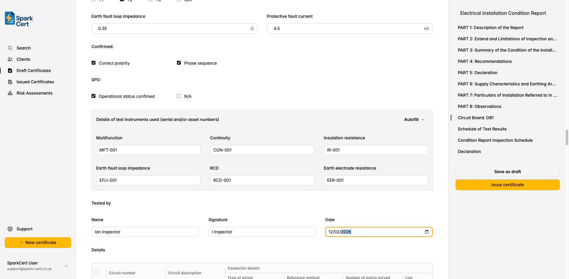
SPD, impedance, and confirmations
Select the surge protection device type: T1, T2, T3, or N/A if no SPD is fitted.
The earth fault loop impedance at the distribution board, in ohms.
The protective fault current at the distribution board, in kA.
Tick to confirm correct polarity at the distribution board.
Confirm correct phase sequence for three-phase installations. Select Yes, No, or N/A for single-phase.
Two checkboxes: tick Operational status confirmed to confirm the SPD is functioning correctly, or tick N/A if no SPD is fitted.
Test instruments
Record the serial or asset numbers of the instruments used for testing. Use the autofill button to populate these from your saved instrument details.
Serial/asset number of the multifunction tester.
Serial/asset number of the continuity tester (if separate from multifunction).
Serial/asset number of the insulation resistance tester.
Serial/asset number of the loop impedance tester.
Serial/asset number of the RCD tester.
Serial/asset number of the earth electrode resistance tester (if applicable).
Tested by
Full name of the person who carried out the testing.
Typed signature for the digital certificate.
The date the testing was carried out. Defaults to today's date.
Circuit details table
Below the board header is a spreadsheet-style table where you enter the test results for each circuit. Add a row for every circuit in the distribution board.
Circuit identification
The circuit number or identifier as marked on the distribution board.
What the circuit supplies - e.g. "Ring final - kitchen sockets", "Lighting - first floor".
Conductor details
The cable or wiring system used for the circuit.
The cable installation method per BS 7671 (e.g. A, B, C, 100, 101, 102). This affects the cable's current-carrying capacity.
How many outlets, luminaires, or connection points are on this circuit.
The cross-sectional area of the live conductors in mm².
The cross-sectional area of the circuit protective conductor in mm².
Overcurrent protective device
The standard number for the overcurrent protective device.
The type characteristic of the device - typically B, C, or D for MCBs.
The current rating of the device in amps.
The rated short-circuit breaking capacity of the device in kA.
The maximum permitted earth fault loop impedance for this protective device, in ohms.
RCD
The standard number for the RCD.
The RCD type: A, AC, B, or F.
The rated residual operating current in milliamps - typically 30mA for additional protection.
The rated current of the RCD in amps.
Continuity (Ω)
Resistance of the line conductor.
Resistance of the neutral conductor.
Resistance of the circuit protective conductor.
The measured resistance of the line conductor plus the circuit protective conductor. Used to verify Zs.
The resistance of the circuit protective conductor alone.
Insulation resistance
The voltage used for the insulation resistance test - typically 500V for circuits up to 500V.
Insulation resistance between live conductors (line to neutral). Minimum acceptable value is 1MΩ.
Insulation resistance between live conductors and earth. Minimum acceptable value is 1MΩ.
Polarity, earth fault loop impedance, RCD, and AFDD
Polarity test result - select N/A, Pass, or Fail.
The highest earth fault loop impedance measured at any point on the circuit. Must not exceed the maximum permitted Zs for the protective device fitted.
The measured disconnection time when tested at rated residual current.
Whether the RCD trips when its test button is pressed - select N/A, Pass, or Fail.
Whether the arc fault detection device trips when its test button is pressed - select N/A, Pass, or Fail.
Tip: You can add multiple distribution boards by clicking the "Add board" button in the Schedule of Test Results section. Each board gets its own header, test instruments, and circuit table.
Final declaration
The final declaration is signed by the person who compiled the condition report inspection schedule and test results. This confirms the accuracy of the schedule data.
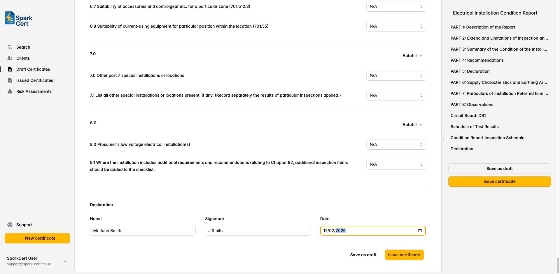
Full name of the person signing the final declaration.
Typed signature for the digital certificate.
The date the declaration was signed.
Installation images
You can attach up to 30 photographs to the report. These are embedded directly into the generated PDF under an “Installation Images” section, making them a permanent part of the report record.
Click the upload area at the bottom of the form to select one or more images. Accepted formats are JPEG, PNG, and WebP, up to 10 MB each. Images are saved immediately - they are not part of the form’s autosave cycle.
Each image has an optional caption field. Use captions to reference specific observations or defects - for example “C2: Exposed wiring at junction box, first floor landing” or “Main earthing conductor connection”. Captions appear beneath the corresponding image in the PDF.
Drag and drop images to change the order they appear in the PDF. Hover over an image and click the red cross to remove it.
Tip: Photographs are particularly valuable on EICRs. Documenting defects with photos gives the client clear evidence of what was found and can help resolve disputes about the condition of the installation at the time of inspection.
Issuing the certificate
Once you've completed all sections, the inspection schedule, and your distribution board test results, review the report for accuracy and issue it. Issuing the certificate locks it to prevent accidental edits, and you can then download the PDF or email it directly to your client from SparkCert.
If you need to make corrections after issuing, you can unlock the certificate, make your changes, and re-issue it.